Semi-automated heat exchanger tube cleaning assembly and method

a technology of semi-automated heat exchangers and cleaning methods, which is applied in the direction of flush cleaning, lighting and heating apparatus, instruments, etc., can solve the problems of all piping and tubing found in industrial facilities, the surface of heat exchangers tend to develop residues, and the adverse effect of residues on the operation performance of heat exchangers

Active Publication Date: 2012-03-22
HYDROCHEM
View PDF3 Cites 40 Cited by
  • Summary
  • Abstract
  • Description
  • Claims
  • Application Information

AI Technical Summary

Benefits of technology

[0008]Various illustrative embodiments of a heat exchanger tube cleaning assembly and method are provided herein. In an illustrative embodiment, an assembly for cleaning one or more tubes on a tube sheet of a heat exchanger is provided. A first trolley and a second trolley can each be disposed on a track. The first trolley and second trolley can be capable of independent movement along the track. A cleaning device can be disposed on either the first trolley or the second trolley. The cleaning device can be being alignable with a selected tube on the heat exchanger tube sheet to be cleaned. A distancer can be disposed between the first trolley and the second trolley. The distancer can be capable of moving either trolley along the track to adjust the distance therebetween. In certain embodiments, the distancer can be a pneumatic cylinder with a movable piston disposed therewithin. The cleaning device can be a cleaning lance. A spacing rod can be dispose...

Problems solved by technology

Over time, these heat exchangers tend to develop residue on the surfaces of the tubes, tube sheets, tube support plates and other internal structural parts.
Over time, this residue can have an adverse affect on the operational performance of the exchangers.
The same problem can arise for all pipi...

Method used


Image

  • Semi-automated heat exchanger tube cleaning assembly and method
  • Semi-automated heat exchanger tube cleaning assembly and method
  • Semi-automated heat exchanger tube cleaning assembly and method

Examples


Embodiment Construction

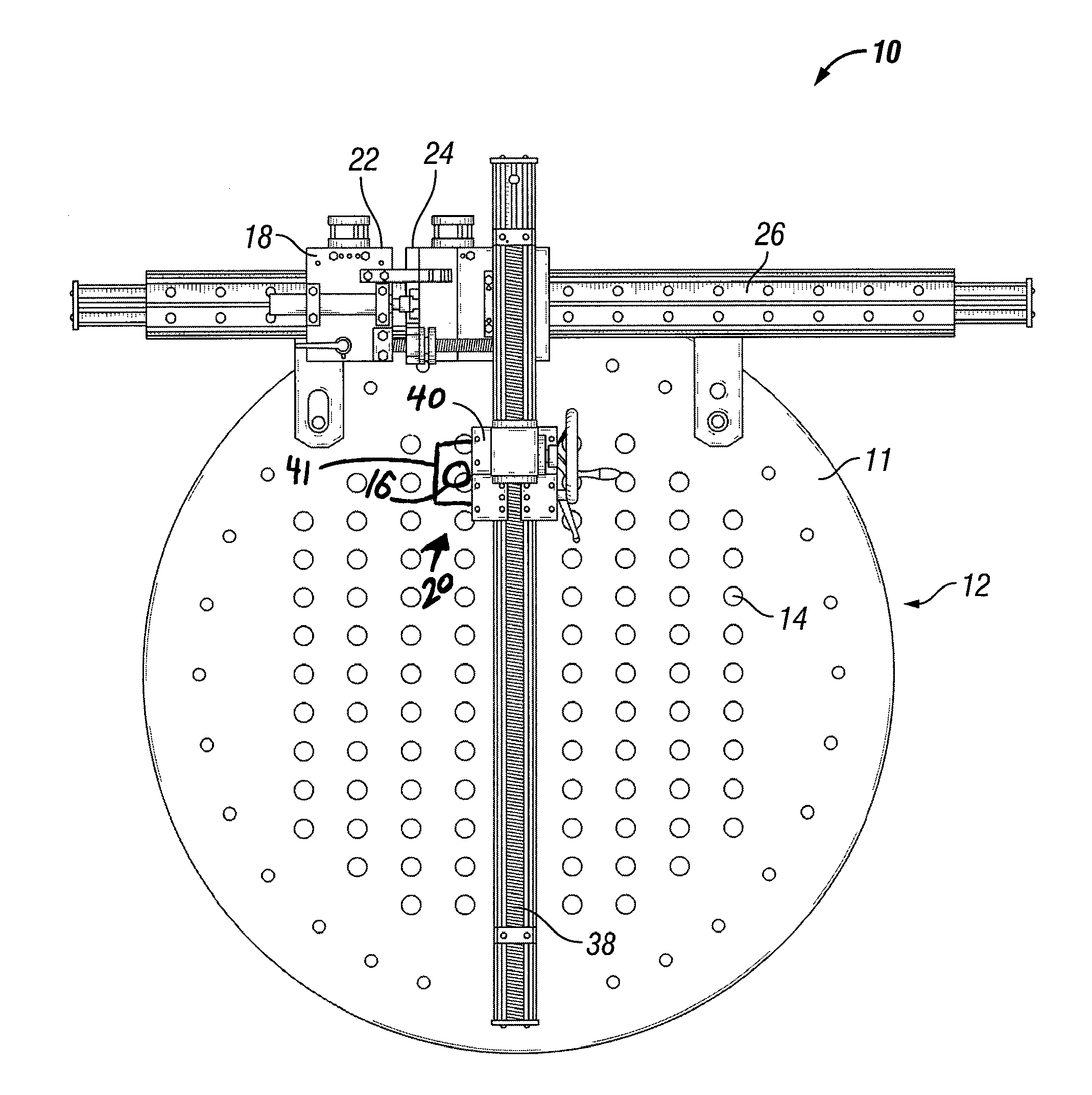
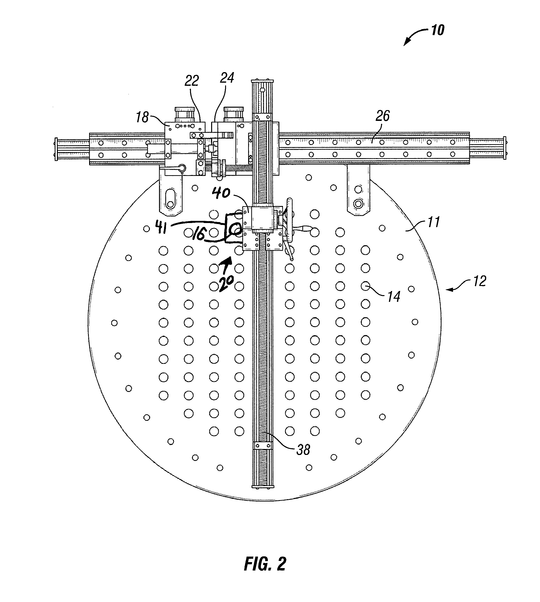
[0030]Referring now to FIGS. 1-15, illustrative embodiments of a heat exchanger tube cleaning assembly and method are provided. Assembly 10 can allow for semi-automated tube cleaning of a heat exchanger 12 or other piping or equipment used in an industrial facility such as, for example, a petrochemical plant or oil refinery.

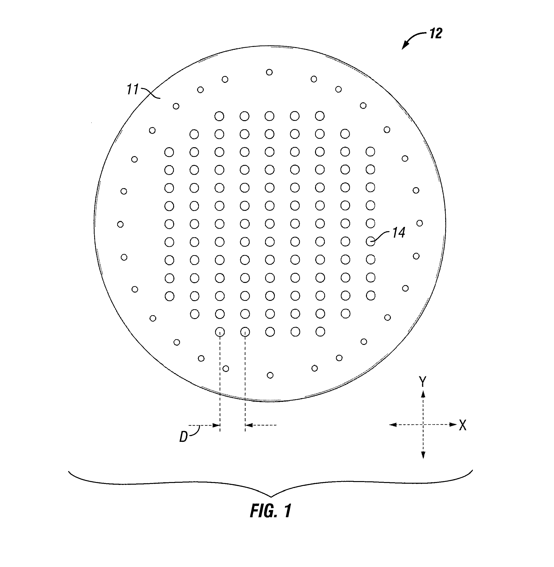
[0031]FIG. 1 shows an illustrative embodiment of a heat exchanger 12 which can be cleaned using assembly 10. A plurality of tubes 14 having flow passageways are exposed on a tube sheet 11 of exchanger 12. Residue can accumulate in or near, among other areas, the flow passageways of tubes 14. Tube sheet 11 is shown having a plurality of tubes 14 aligned in tube rows, whereby tubes 14 are generally oriented in a square pitch. The horizontal distance between the center points of each tube 14 in a particular tube row is indicated by the distance D. Tube sheet 11 and exchanger 12 can be disposed in a variety of possible positions, including horizontal or vertical orie...


PUM


Abstract

A heat exchanger tube cleaning assembly and method is provided. The assembly can allow for semi-automated tube cleaning of a heat exchanger or other piping or equipment used in an industrial facility such as, for example, a petrochemical plant or oil refinery.

Description

RELATED APPLICATIONS [0001]This application claims the benefit, and priority benefit, of U.S. Provisional Patent Application Ser. No. 61 / 383,965, filed Sep. 17, 2010, titled “Semi-Automated Heat Exchanger Tube Cleaning Assembly and Method,” the disclosure of which is incorporated herein in its entirety.BACKGROUND [0002]1. Field of Invention[0003]This invention relates generally to the cleaning of heat exchangers, and more particularly, to an assembly and method for semi-automated tube cleaning for a heat exchanger or other piping or equipment used in an industrial facility such as, for example, a petrochemical plant or oil refinery.[0004]2. Description of the Related Art[0005]Heat exchangers are commonly used in industrial facilities. Over time, these heat exchangers tend to develop residue on the surfaces of the tubes, tube sheets, tube support plates and other internal structural parts. Over time, this residue can have an adverse affect on the operational performance of the exchan...

Claims


Application Information

Patent Timeline
IPC IPC(8): B08B9/04G01N33/00
CPCB08B9/043F28G15/04F28G15/02F28G1/16F28G1/163F28G1/166F28G3/16F28G3/163F28G3/166F28G9/00F28G9/005
Inventor CROCK, TERRY LEEMOLL, FRANK JOSEPHBUCHANAN, JAMES
Owner HYDROCHEM
Why Eureka
Try Eureka