Hydraulic system for working machine

a working machine and hydraulic system technology, applied in the direction of braking systems, couplings, servomotors, etc., can solve the problems of low system efficiency, poor straightness in running, and no third pump driven, so as to ensure the straightness of running and turning performance of the working machine, and ensure the straightness of running and turning performance. , the effect of ensuring the straightness of running and turning performan

Active Publication Date: 2012-03-22
KUBOTA LTD
View PDF7 Cites 15 Cited by
  • Summary
  • Abstract
  • Description
  • Claims
  • Application Information

AI Technical Summary

Benefits of technology

[0043]According to the first aspect of the present invention, in the hydraulic system in which the left and right track drive motors, the dozer cylinder, and other hydraulic actuators included in the working machine can be driven by the hydraulic fluid from the two independent hydraulic-fluid discharge ports, the straightness in running and the turning performance of the working machine can be ensured at the time when the dozer device is operated while the working machine is running.
[0044]That is, in a case where the dozer device is operated while the working machine is running, hydraulic fluid from one of the hydraulic-fluid discharge ports is independently supplied to one of the track control valves and one of the dozer control valves, and hydraulic fluid from the other of the hydraulic-fluid discharge ports is independently supplied to the other of the track control valves and the other of the dozer control valves. At this time, the hydraulic fluid from the one of the hydraulic-fluid discharge ports and the hydraulic fluid from the other of the hydraulic-fluid discharge ports are evenly drawn by the pair of dozer control valves concurrently operated, and then the drawn hydraulic fluid is sent to the dozer cylinder. Therefore, the straightness in running of the working machine can be ensured.
[0045]Moreover, in a case where the working machine is turned left or right while the dozer device is being operated, the pressure compensation valves control the distribution of the flow rate. Therefore, even when the loads applied to the track drive motors are high, and the load applied to the dozer cylinder is low, the hydraulic fluid exceeding a set flow rate does not flow into the dozer cylinder. Therefore, an independent circuit configuratio...

Problems solved by technology

However, when the dozer cylinder or the like is not operated, the third pump is driven to no avail.
This results in low system efficiency.
This results in a poor straightness in running and extremely poor turning performance.
How...

Method used


Image

  • Hydraulic system for working machine
  • Hydraulic system for working machine
  • Hydraulic system for working machine

Examples


Embodiment Construction

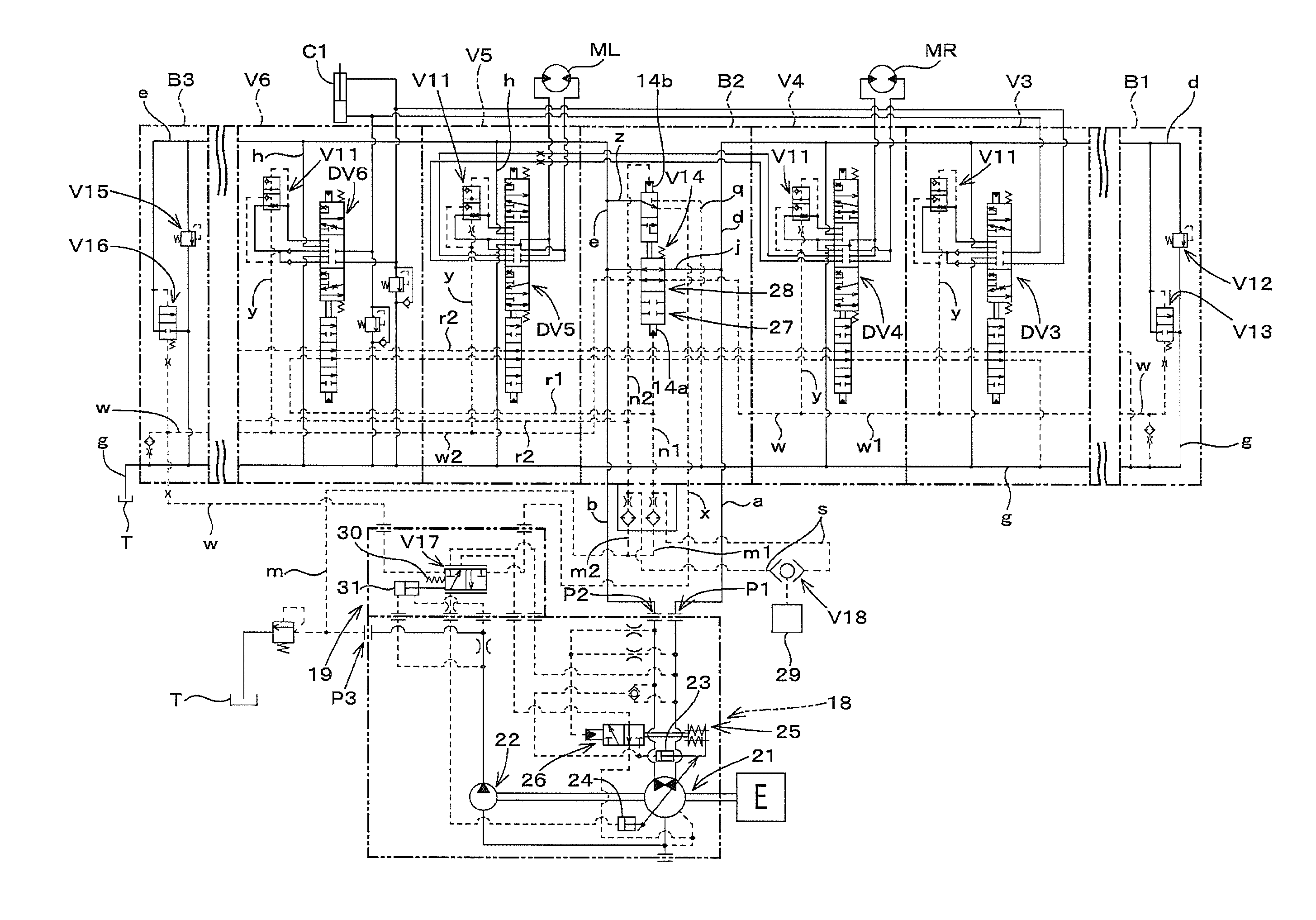
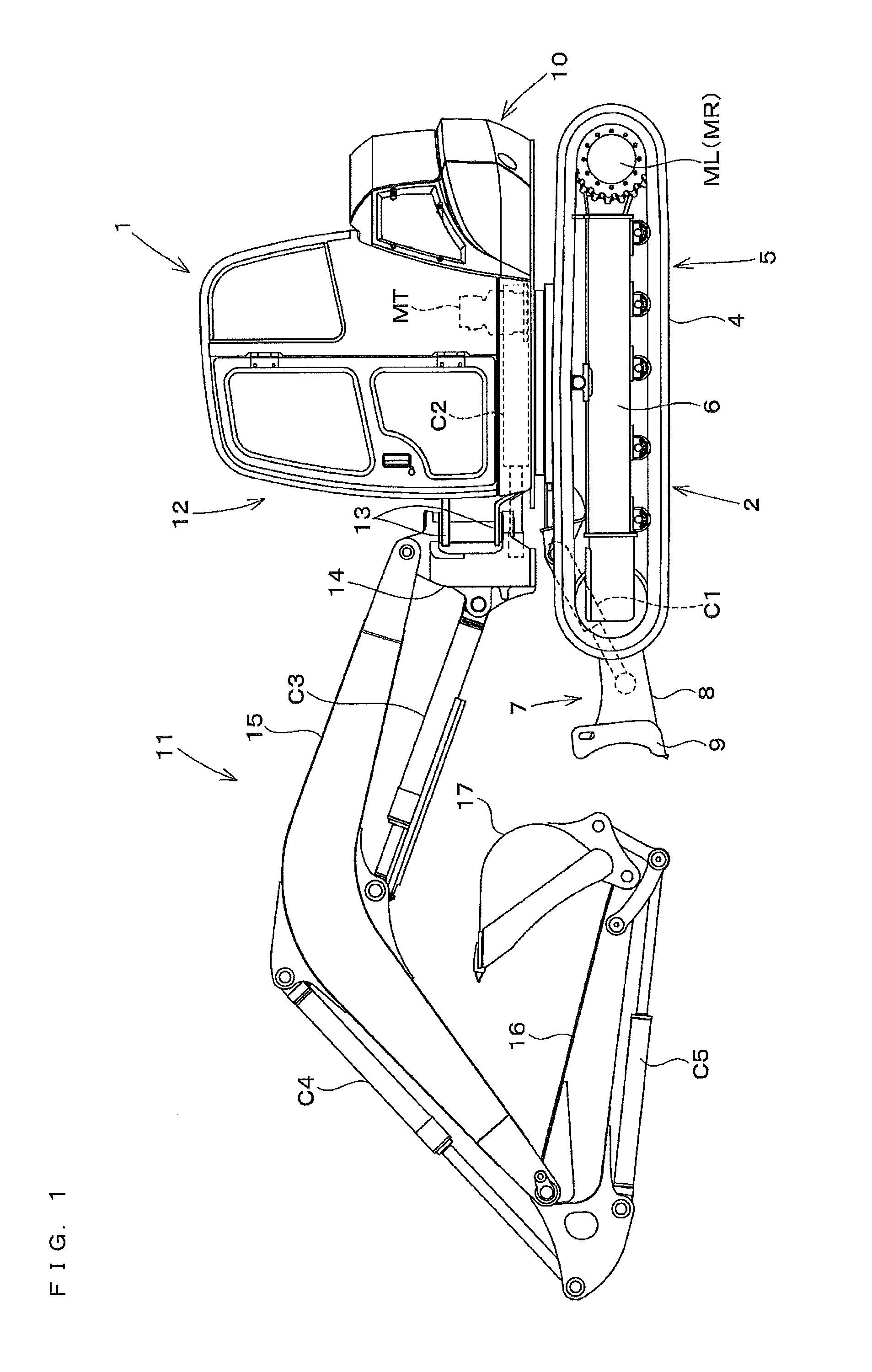
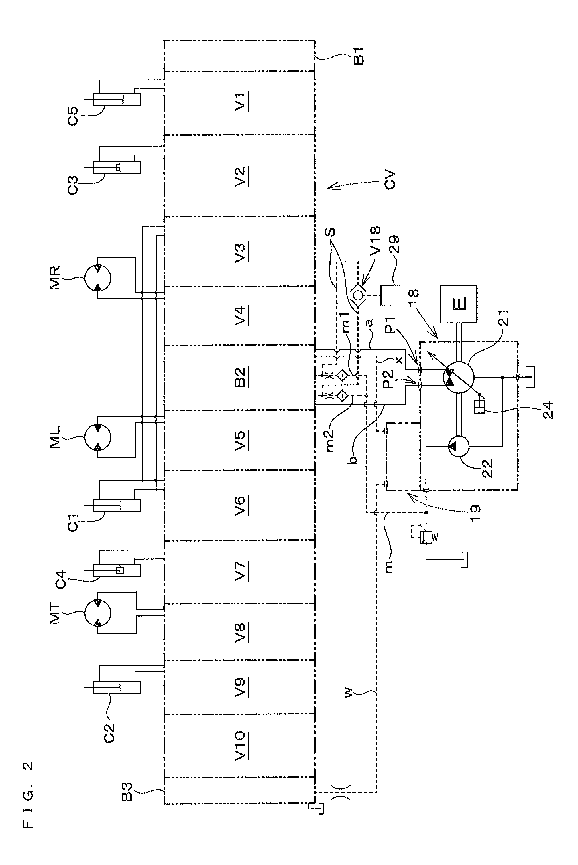
[0057]Hereinafter, an embodiment of the present invention will be described with reference to the drawings. FIG. 1 is a side view showing a backhoe employing a hydraulic system according to the present invention. FIG. 2 is a schematic diagram showing an embodiment of the hydraulic system according to the present invention. FIG. 3 is a hydraulic circuit diagram showing the embodiment of the hydraulic system according to the present invention. FIG. 4 is a hydraulic circuit diagram showing a part of the hydraulic system shown in FIG. 3. FIG. 5 is a hydraulic circuit diagram showing another part of the hydraulic system shown in FIG. 3. FIG. 6 is a hydraulic circuit diagram showing still another part of the hydraulic system shown in FIG. 3. FIG. 7 is a hydraulic circuit diagram showing a flow control section and a hydraulic fluid supply unit in the hydraulic system shown in FIG. 3.

[0058]In FIG. 1, reference numeral 1 denotes a backhoe (working machine). The backhoe 1 is mainly composed o...


PUM


Abstract

A pair of dozer control valves V3, V6 concurrently operable; a pilot pressure valve V14 switchable between an independent position 27 where, when only track devices 5 are operated, discharged fluid from one hydraulic-fluid discharge port P1 is independently supplied to one track control valve and one dozer control valve, and discharged fluid from the other hydraulic-fluid discharge port P2 is independently supplied to the other track control valve and the other dozer control valve, and a merging position 28 where, when the other control valves are operated, discharged fluid from the one hydraulic-fluid discharge port and from the other hydraulic-fluid discharge port are merged and supplied to the control valves V1 to 10; and pressure compensation valves V11 in the control valves and for distributing hydraulic fluid at flow rates based on extent of actuation of the other control valves operated, irrespective of the magnitude of the loads.

Description

CROSS REFERENCE TO RELATED APPLICATION[0001]The disclosure of Japanese Patent Application No. 2010-210938, filed on Sep. 21, 2010, is incorporated herein by reference.BACKGROUND OF THE INVENTION[0002]1. Field of the Invention[0003]The present invention relates to hydraulic systems for working machines, and in particular, to hydraulic systems for working machines provided with a pair of track devices and a dozer device.[0004]2. Description of the Background Art[0005]Working machines provided with a pair of track devices and a dozer device, such as, for example, the working machine disclosed in Japanese Laid-Open Patent Publication No. 2006-161510, have been proposed to date.[0006]The working machine according to this reference is provided with a swivel base configured to swivel about a vertical axis on a track body which is equipped with a dozer device on a front part thereof, and a digging device furnished on a front part of the swivel base.[0007]The track body includes a pair of le...

Claims


Application Information

Patent Timeline
IPC IPC(8): F15B13/06
CPCE02F9/2239E02F9/2292E02F9/2296F15B11/163F15B2211/6355F15B2211/20553F15B2211/20576F15B2211/30555F15B11/165Y10T137/87265E02F9/22F15B13/02
Inventor HORII, HIROSHI
Owner KUBOTA LTD
Why Eureka
Try Eureka