Heat exchanger unit and thermotechnical system

a technology of heat exchanger unit and thermotechnical system, which is applied in the direction of heat pump, separation process, lighting and heating apparatus, etc., can solve the problems of high capital-intensive chp technology (combined heat and power), low system utilization during the summer months, etc., and achieve material- and cost-saving structure. , the effect of saving the cost and provisions of the droplet separator

Active Publication Date: 2012-03-22
TECHNICAL UNIVERSITY OF BERLIN
View PDF7 Cites 0 Cited by
  • Summary
  • Abstract
  • Description
  • Claims
  • Application Information

AI Technical Summary

Benefits of technology

[0018]One advantageous configuration of the invention provides for a droplet separator-free design. In contrast to known heat exchanger units, costs and provisions for a droplet separator can be saved.
[0019]

Problems solved by technology

An obstacle for the increased expansion of capital-intensive CHP technologies (

Method used


Image

  • Heat exchanger unit and thermotechnical system
  • Heat exchanger unit and thermotechnical system
  • Heat exchanger unit and thermotechnical system

Examples


Embodiment Construction

[0022]The invention is explained in more detail hereinafter by means of preferred exemplary embodiments with reference to figures of a drawing. In the figures:

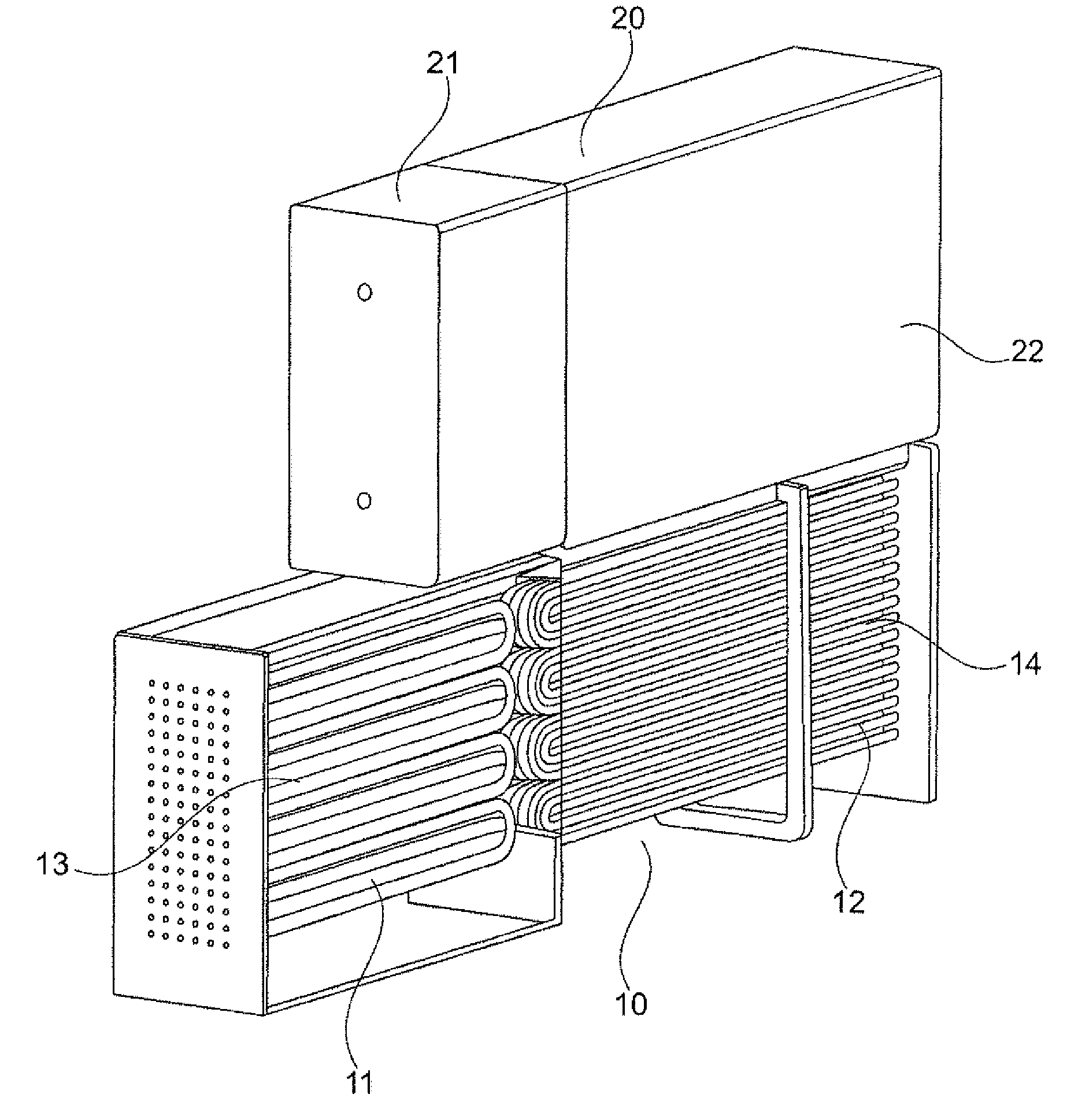
[0023]FIG. 1 shows a perspective illustration of a thermotechnical system comprising four heat exchanger components,

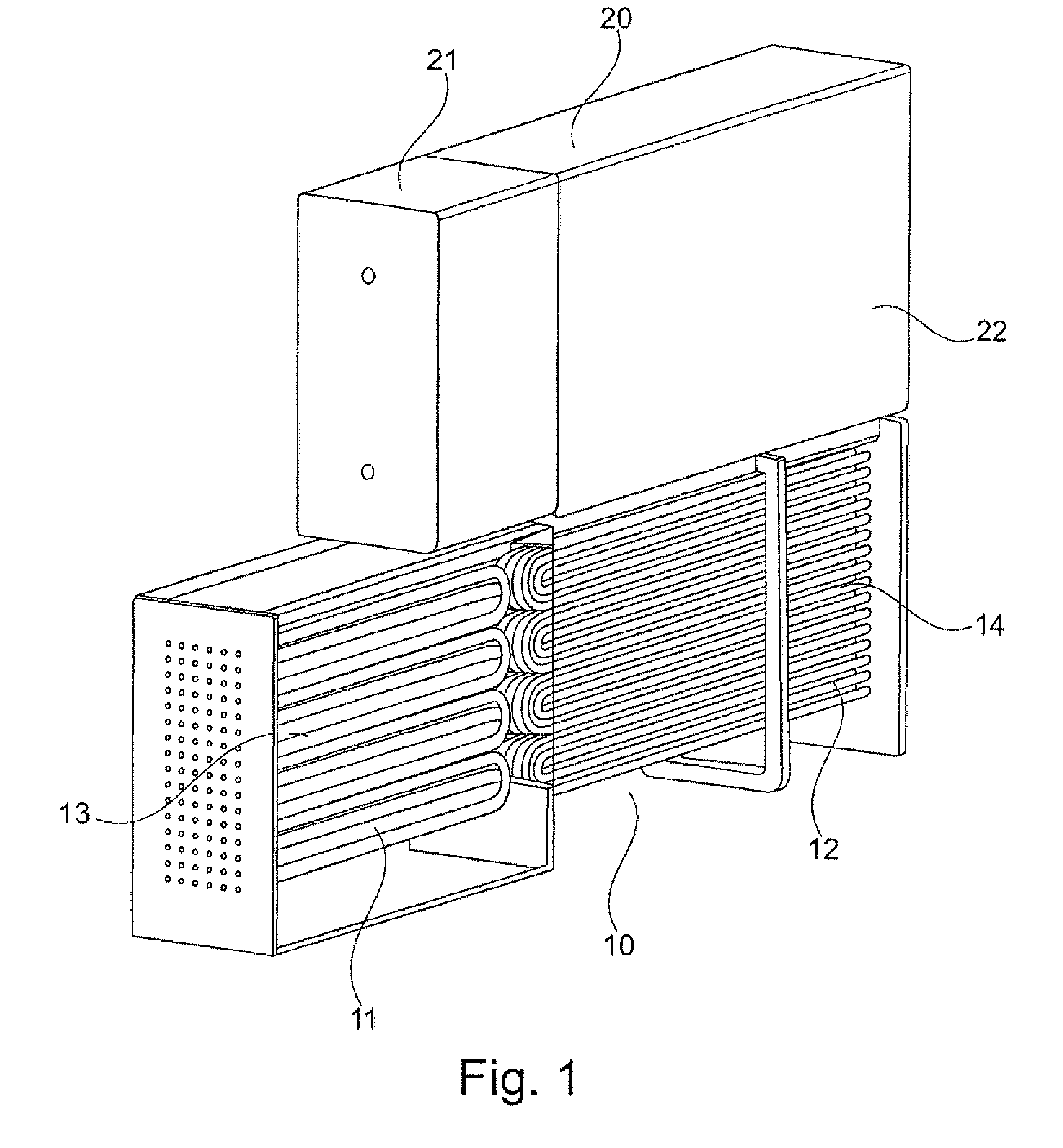
[0024]FIG. 2 shows a schematic illustration of a heat exchanger unit comprising a condenser device and an evaporator device, wherein the front faces are arranged opposing each other,

[0025]FIG. 3 shows a schematic illustration of a heat exchanger unit comprising a condenser device and an evaporator device, wherein the front faces are likewise arranged opposing each other, and

[0026]FIG. 4 shows a schematic illustration of a heat exchanger unit comprising a condenser device and an evaporator device in a frontal configuration, wherein the evaporator device and the condenser device are arranged partially meshing with each other.

[0027]FIG. 1 shows a perspective illustration of a thermotechnical system comprising a heat...


PUM


Abstract

The invention relates to a heat exchanger unit having an evaporator device configured for evaporating a heat exchanger operating fluid, and a condenser device for condensing the heat exchanger operating fluid, wherein the evaporator device and the condenser device are fluidically connected to each other in a frontal configuration. The invention further relates to a thermotechnical system having a plurality of heat exchanger units.

Description

[0001]The invention relates to a heat exchanger unit and to a thermotechnical system, in particular a refrigeration system.BACKGROUND OF THE INVENTION[0002]The demand for air-conditioning, in particular cooling energy, and thus the total energy demand is constantly and significantly increasing due to increasing workplace requirements and desires for comfort. Air conditioning in automotive technology for the private or commercial sector with respect to the passenger compartment has increased within the last 10 years from a marginal market share and has reached nearly 100%. A similar development is to be expected for air-conditioning in existing buildings. In addition, with the implementation of the European directive on total energy efficiency of buildings, the cooling energy demand is considered in the future in the assessment of buildings. Thus, energy- and cost-efficient cooling technologies become more and more important.[0003]An obstacle for the increased expansion of capital-in...

Claims


Application Information

Patent Timeline
IPC IPC(8): F28D7/00F25B30/00C02F1/04F25B1/00
CPCF25B39/00F28D1/0426F28D2021/0071F28D1/0478F28D2021/007F28D1/0443
Inventor PETERSEN, STEFANFINCK, CHRISTIANMITTERMAIER, MARTINJAHNKE, ANNA
Owner TECHNICAL UNIVERSITY OF BERLIN
Why Eureka
Try Eureka