Antenna System Monitor

a technology of antenna system and monitor, which is applied in the direction of radio transmission, electrical equipment, transmission, etc., can solve the problems of inability to monitor individual frequency channels within signals, inability to detect changes in the performance of individual channels within transmitted rf spectrum, and inability to generally suit the needs of facilities, so as to reduce the cost of installation

Active Publication Date: 2012-03-22
RF IND
View PDF7 Cites 38 Cited by
  • Summary
  • Abstract
  • Description
  • Claims
  • Application Information

AI Technical Summary

Benefits of technology

[0009]According to another embodiment, the apparatus may include a plurality of forward input ports and corresponding reverse input ports, and first and second RF couplers configured to combine fields received at the forward input ports and reverse input ports respectively. For example, four forward input ports and four reverse input ports may be included in the apparatus in which each pair may be coupled to a separate transmission cable or antenna. At a transmission site, a number of antennas may be provided, each of which covers a different frequency band. By combining monitoring signals from each antenna in such an arrangement within the monitoring apparatus, and prior to coupling of the combined signals into the tunable filter, a single monitoring apparatus may be shared amongst, for example, four antennas. This may reduce the cost of installing appropriate monitoring within the transmitter site.

Problems solved by technology

While most modern high-power transmitters include internal voltage standing wave ratio (VSWR) monitoring and protection, these facilities are not generally suitable for ongoing monitoring of the health of the transmission system which might enable changes in performance to be detected early when they can be prevented from developing into more serious faults.
However, such prior art devices monitor the transmitted RF signal in its entirety, and are not capable of monitoring individual frequency channels within the signal.
Accordingly, they are unable to detect changes in the performance of individual channels within the transmitted RF spectrum.
This results in a relatively high expense of installing a complete monitoring solution at a particular transmitter site.

Method used


Image

  • Antenna System Monitor
  • Antenna System Monitor
  • Antenna System Monitor

Examples


Embodiment Construction

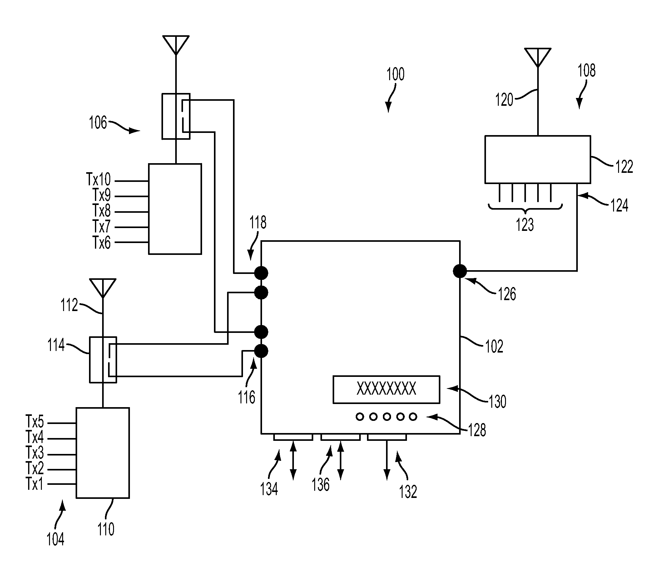
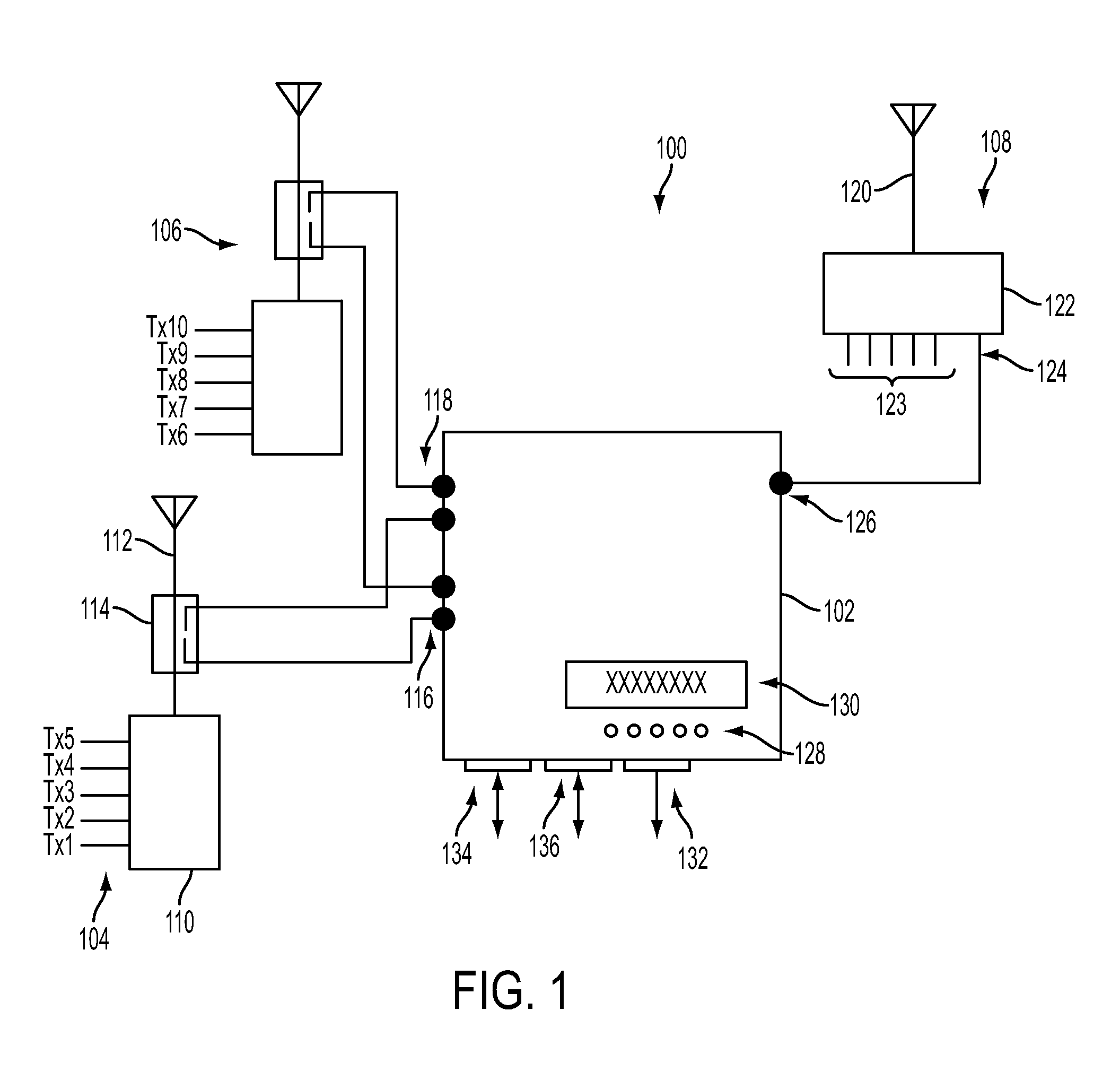
[0027]FIG. 1 is a block diagram illustrating a portion of an RF wireless transmission system 100 incorporating a monitoring apparatus 102. The system 100 includes one or more transmitting antenna units 104, 106. The exemplary system 100 also includes a receiving antenna unit 108. Each transmitting antenna unit 104 may include a transmitter combiner 110, which combines a plurality of transmitted channels having different carrier frequencies for transmission via a single antenna 112. To facilitate monitoring of the transmitted signal by the apparatus 102, a directional coupler 114 may be installed at the antenna 112 for monitoring both forward-propagating and reflected RF fields. Each forward-propagating coupler output may be coupled to a corresponding forward input port 116 of the monitoring apparatus 102, while each reflected field monitoring port may be coupled to a corresponding reverse input port 118. That is, the directional couplers of each transmitting antenna unit 104, 106 ma...


PUM


Abstract

A system is disclosed for monitoring of individual frequency channels in an RF signal band by configuration of the electronic processor to operate the tunable filter to select desired channel sub bands. Measurement of forward and / or reverse-propagating fields within the selected sub-bands may be performed and corresponding power levels recorded. The records may be used to provide monitoring signals, such as measures of forward and reflected power, as well as VSWR, return loss. Indications or alarms may be activated if any of these quantities, associated with any one or more channels, falls outside a predetermined acceptable operating range.

Description

TECHNICAL FIELD[0001]The present invention relates to monitoring the performance and operation of radio frequency (RF) transmission systems.BACKGROUND[0002]Radio frequency (RF) transmission is used in a wide range of communications applications. Without limitation, these applications include terrestrial trunked radio (TETRA), personal communications system (PCS), 3G, advanced mobile phone system (AMPS), broadcast, code division multiple access (CDMA), digital cellular system (DCS), government, general packet radio service (GPRS), global system for mobile communications (GSM), industrial, microwave, military, paging, public safety, rail, ultra-high frequency (UHF), utilities, very high frequency (VHF) and wideband CDMA (W-CDMA). Many of these systems involve the use of fixed transmitters and / or receivers, which may serve large numbers of users and operate at relatively high power levels. In some applications, such as public safety, high availability of the transmission system is esse...

Claims


Application Information

Patent Timeline
Patent Type & Authority Applications(United States)
IPC IPC(8): H04B1/18
CPCH04B7/0814
Inventor JONES, MICHAEL W.VOSKULEN, LAMBERTUS A. M.
Owner RF IND
Why Eureka
Try Eureka