Methods and systems for environmental system control

a technology of environmental system and control method, applied in the direction of instruments, heating types, static/dynamic balance measurement, etc., can solve the problems of not having a detector of stale air, and current technology does not cleanly define ‘stale air’

Inactive Publication Date: 2012-03-22
POWELL KEVIN J +1
View PDF11 Cites 66 Cited by
  • Summary
  • Abstract
  • Description
  • Claims
  • Application Information

AI Technical Summary

Benefits of technology

[0015]The environmental controls interface environmental control equipment that provides environmental conditioning of one or more environmental factors into the space that is the target for human presence. In addition, systems that more directly impact or more efficiently impact one or more of the environmental factors described herein may be controlled. For example, ‘stale’ air may be controlled by the introduction of exterior air, since this is technologically feasible and reasonably efficient, and a future control may be applied to a system that removes carbon dioxide and / or adds oxygen without utilization of exterior air. Equipment manufacturers may use an interface through their own sensor device so that the sensor device may implement other trade secret protection algorithms, such as short cycling, defrost, etc. These algorithms may be accommodated within embodiments, thus replacing the need for a separate and duplicate sensor unit.

Problems solved by technology

However, current technology does not cleanly define ‘stale air’, nor is a detector of stale air present.

Method used


Image

  • Methods and systems for environmental system control
  • Methods and systems for environmental system control
  • Methods and systems for environmental system control

Examples


example embodiments

[0040]The example embodiments described herein are provided for illustrative purposes, and are not limiting. Furthermore, their structural and operational embodiments, including modifications, alterations, will become apparent to persons skilled in the relevant art(s) from the teachings herein.

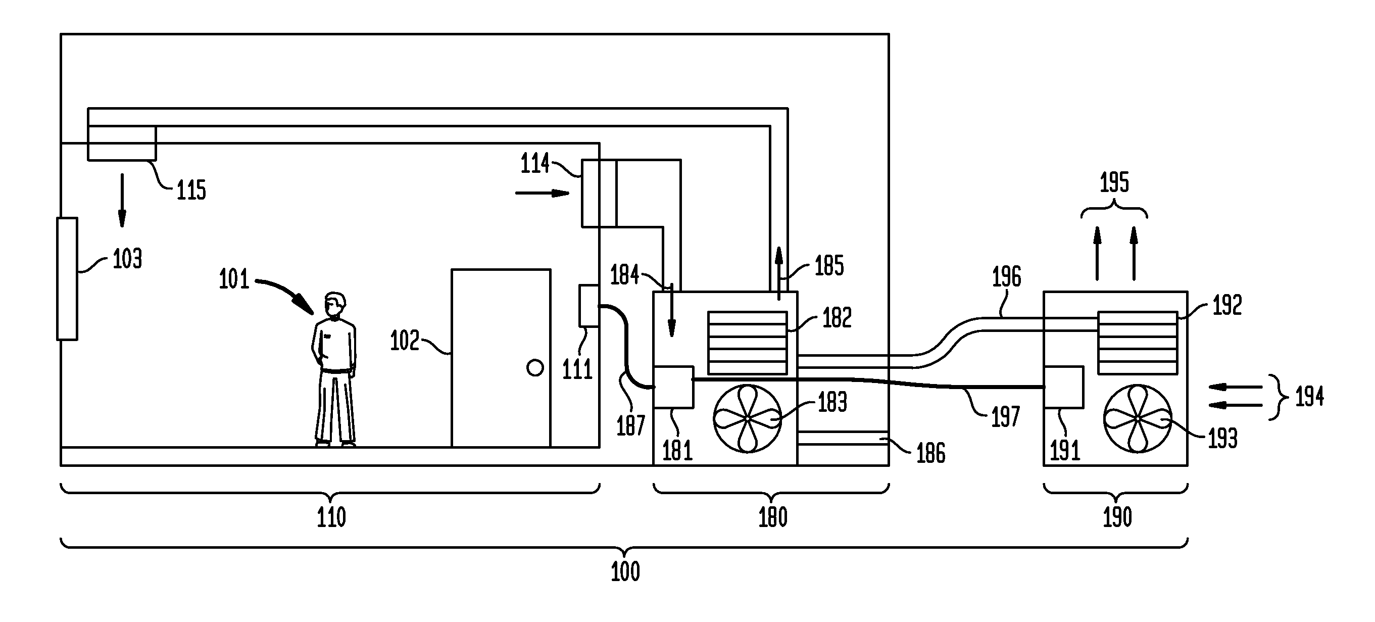
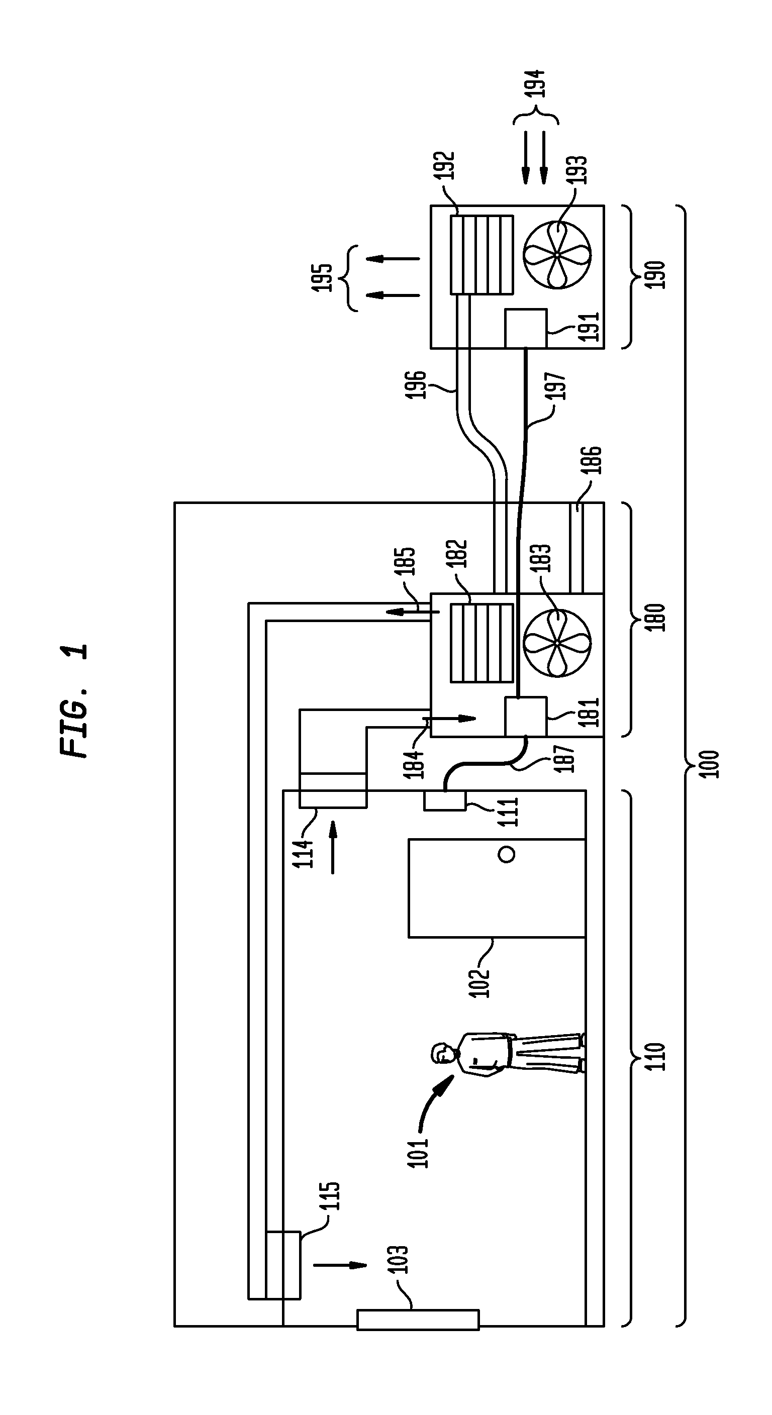
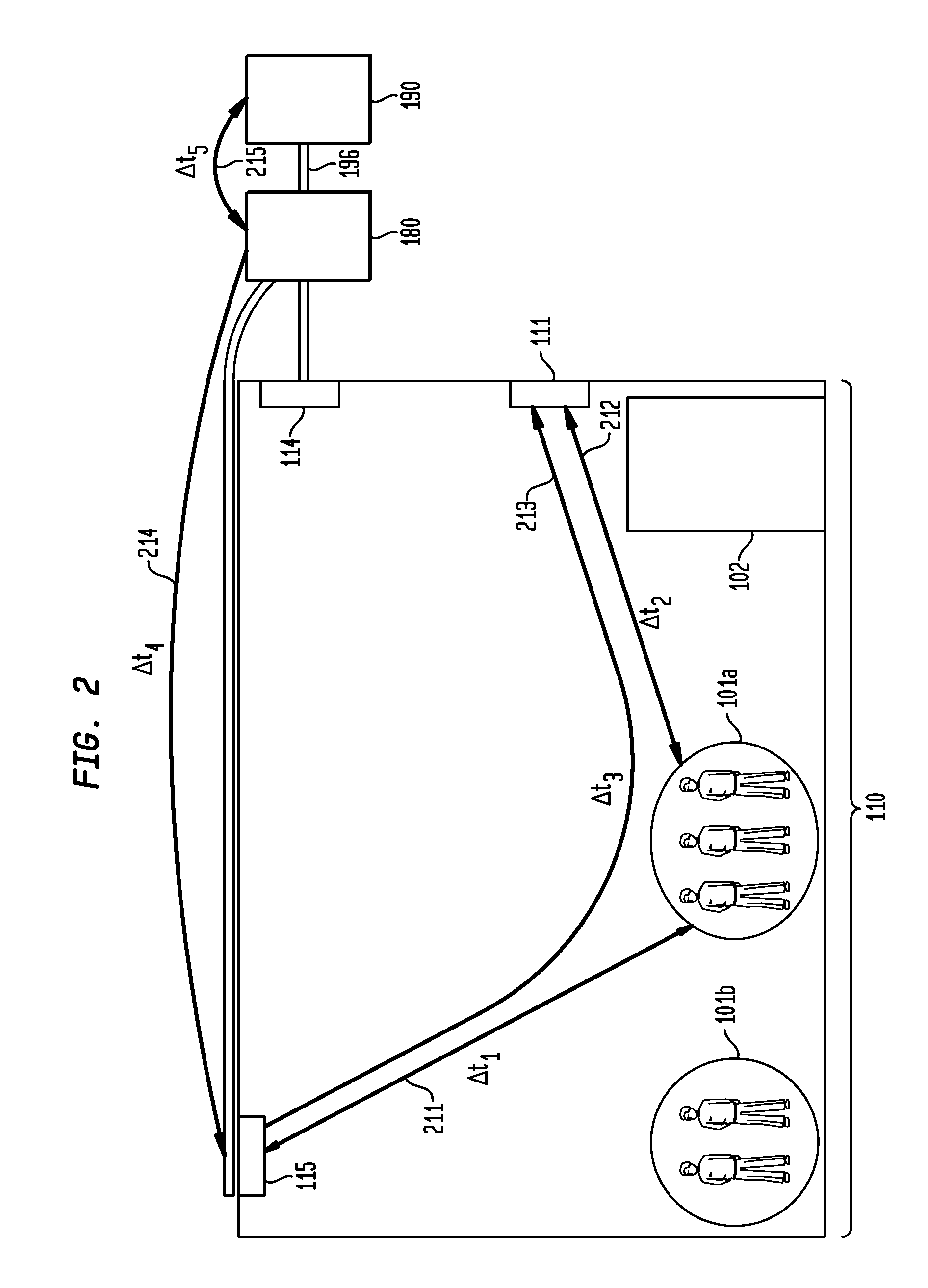
[0041]As described in the background section, current ECSs cause human subjects to experience cyclical swings in the environmental factors around their own personal micro-environment. As a result, the environment is not controlled to a tolerance that maintains a quality comfort level for the human body. As such, in embodiments, an ECS is provided that can ensure that the micro environment that surrounds the human subject(s) is the target of the ECS, rather than the micro-environment surrounding the sensors or conditioned air output. The ECS can directly detect the micro-environment and / or predict the effects of the human on their micro-environment in order to compensate in advance of any under...

example device embodiments

III Example Device Embodiments

[0109]Embodiments, including ECS 400, processing unit 440, power module 420, processor 530, OS and algorithm 550, flowchart 600, and flowchart 700 may be implemented in hardware, software, firmware, or any combination thereof. For instance, one or more of ECS 400, processing unit 440, power module 420, processor 530, OS and algorithm 550, flowchart 600, and flowchart 700 may be implemented in a computing device, such as a computer, a special purpose device, etc. For example, ECS 400, power module 420, OS and algorithm 550, flowchart 600, and flowchart 700 may be implemented as computer program code configured to be executed in one or more processors. Alternatively, ECS 400, processing unit 440, power module 420, processor 530, OS and algorithm 550, flowchart 600, and flowchart 700 may be implemented as hardware logic / electrical circuitry. For instance, in an embodiment, one or more of ECS 400, processing unit 440, power module 420, processor 530, OS and...


PUM


Abstract

Methods, systems, and apparatuses for environmental system controls are provided. A number of human subjects present within a space is determined, which may include counting the human subjects and / or determining a thermal mass of the human subjects. An impact upon an environmental factor by the present human subjects upon the space is determined. Environmental conditioning equipment is controlled based on the determination.

Description

[0001]This application claims the benefit of U.S. Provisional Application No. 61 / 385,203, filed on Sep. 22, 2010, which is incorporated by reference herein in its entirety.BACKGROUND OF THE INVENTION[0002]1. Field of the Invention[0003]The present invention relates to environmental control systems.[0004]2. Background Art[0005]The human micro-environment: Environmental Control Systems (ECSs) are currently engineered to provide heating, ventilation, and cooling in order to maintain a comfortable environment for humans. ECSs in use today include sensors to detect a variety of environmental factors, heat exchangers in combination with air handlers (fans) on the interior of the building, exterior heat exchange equipment (compressors, chillers, etc), and control logic. These current ECSs are designed with sensors monitoring the environment in locations that are convenient for construction (such on as a wall, inside an air duct, etc.), but are not necessarily located in the spaces where hu...

Claims


Application Information

Patent Timeline
Patent Type & Authority Applications(United States)
IPC IPC(8): G05D23/19G06K9/00
CPCF24F2011/0071F24F11/0034F24F11/30F24F2120/10F24F11/58F24F11/64
Inventor POWELL, KEVIN J.GILSTRAP, DANIEL
Owner POWELL KEVIN J
Why Eureka
Try Eureka