Power device

a power device and circuit technology, applied in the direction of dc-ac conversion without reversal, process and machine control, instruments, etc., can solve the problems of large power waste, inability to achieve anything, waste electricity, devices and appliances continue to draw current, etc., to achieve the effect of conserving energy

Active Publication Date: 2015-12-01
SMART PRONG TECH INC
View PDF13 Cites 7 Cited by
  • Summary
  • Abstract
  • Description
  • Claims
  • Application Information

AI Technical Summary

Benefits of technology

[0025]This invention works for both battery powered devices and direct powered devices. With a communication chip included in the SmartProng™ Technology Plug / cord, powered appliances can receive a command to shut-off the appliance / device at certain times (usually designated as “Demand Response” times by the Electrical Utility) and thus cover the entire plug load market with added energy efficiency.
[0027]This invention is a method for a design and utility patent for “Pre-Regulating” power current loads for devices which makes transformers obsolete, and regulating battery fulfillment, turning-off power when the battery is full and saving wasted energy.
[0030]The present invention utilizes capacitor drop technology, by housing it in or connected directly to the plug prong or prongs, which are then plugged into and AC outlet, makes the prongs themselves one or more capacitors. One advantage is that the voltage leaving the outlet socket is limited right from the start. This conserves energy and makes the SmartProng Plug safer. Thus safety and efficiency are embodied in a new and unique way into the same product. The miniature capacitors which are either embedded into one or more prongs or are connected to one or more prongs and housed in the plug can have a fixed value, like a plug that only delivers 5 volts AC at 1 Amp which would be the 5 watts needed to charge a cell phone. Or a fixed value could deliver 10 volts AC at 2 Amps for the 12 watts needed to power an iPad or similar notebook. Alternatively, the capacitance can be housed on the circuit board, replacing the need for the transformer and linear regulator combination.
[0033]The invention modifies and controls the capacitance of a capacitor drop system, and eliminates the need for the transformer linear regulator combination at the end of the chain. Instead, it controls the amount of current (amp×volts) that exits by frequency modulation.

Problems solved by technology

Also call “Wall Wort Power” or “Standby Power” this electricity waste makes up a large portion of homes' or offices' miscellaneous electric load and is a large waste of power.
All this means that even when a cell phone, lap top or like device is completely charged, current is still flowing, but not accomplishing anything and wasting electricity.
Most recently manufactured devices and appliances continue to draw current all day, every day—and cost you money and add to the Energy Crisis Worldwide.
“The impact of plug loads on overall consumption is quite significant.

Method used


Image

  • Power device
  • Power device
  • Power device

Examples


Embodiment Construction

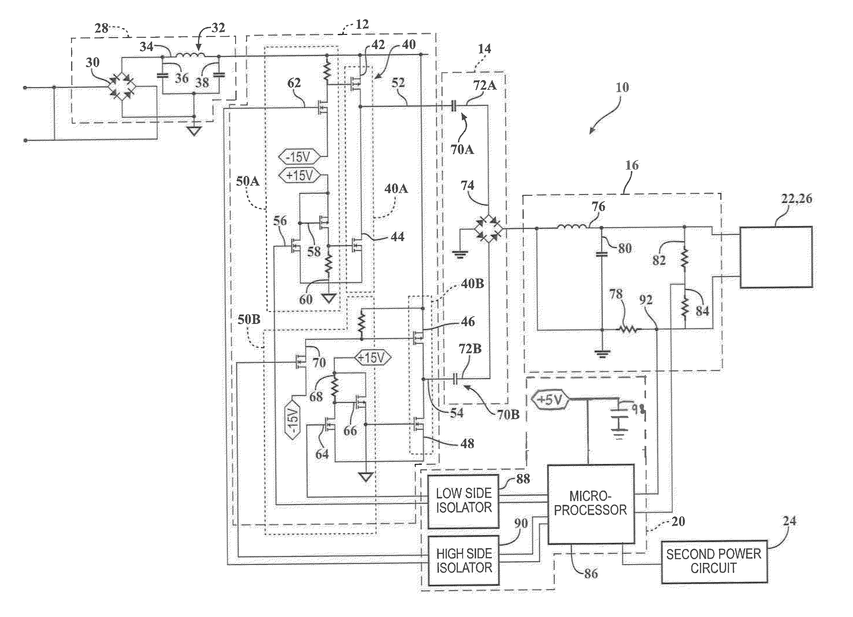
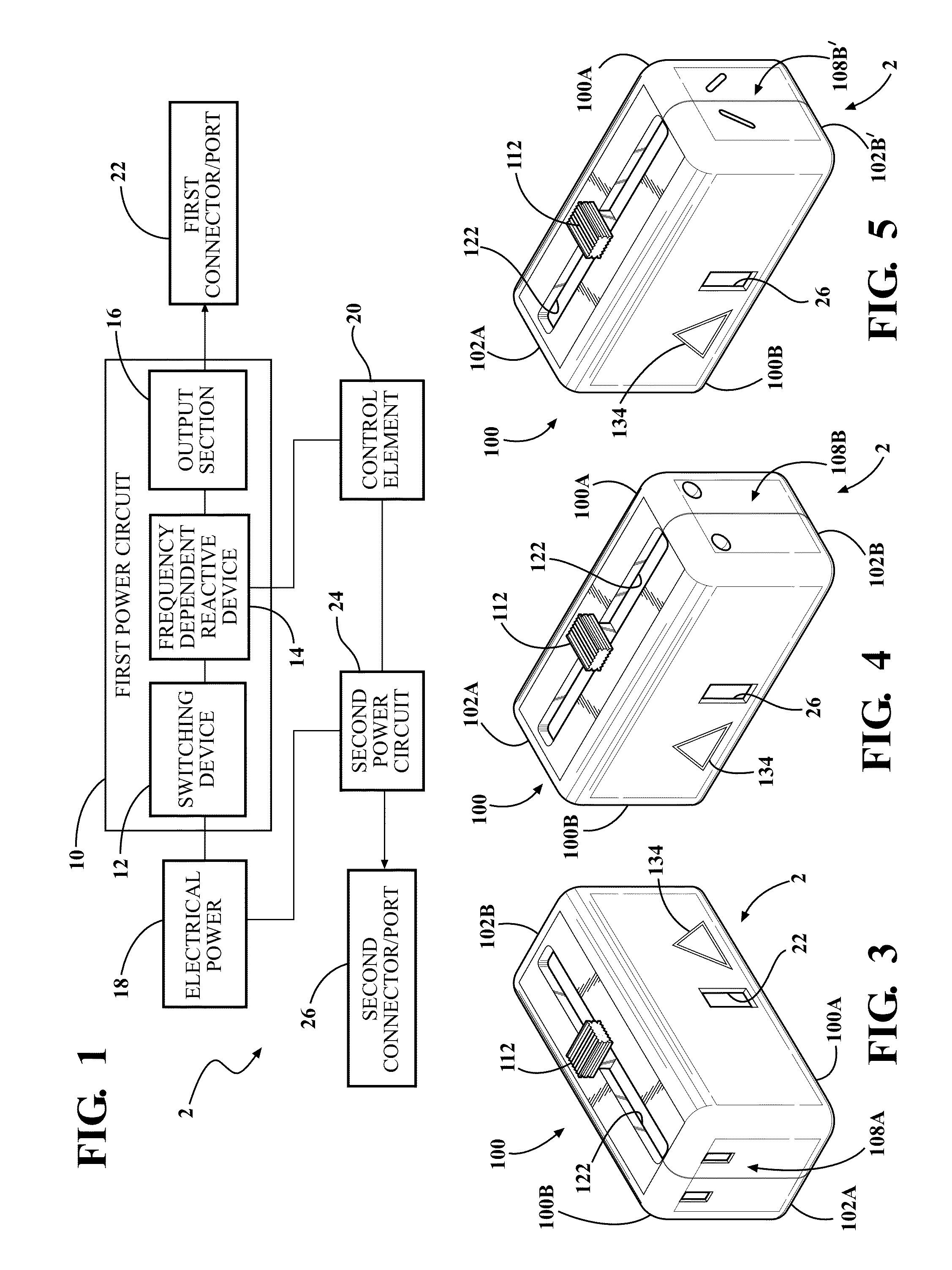
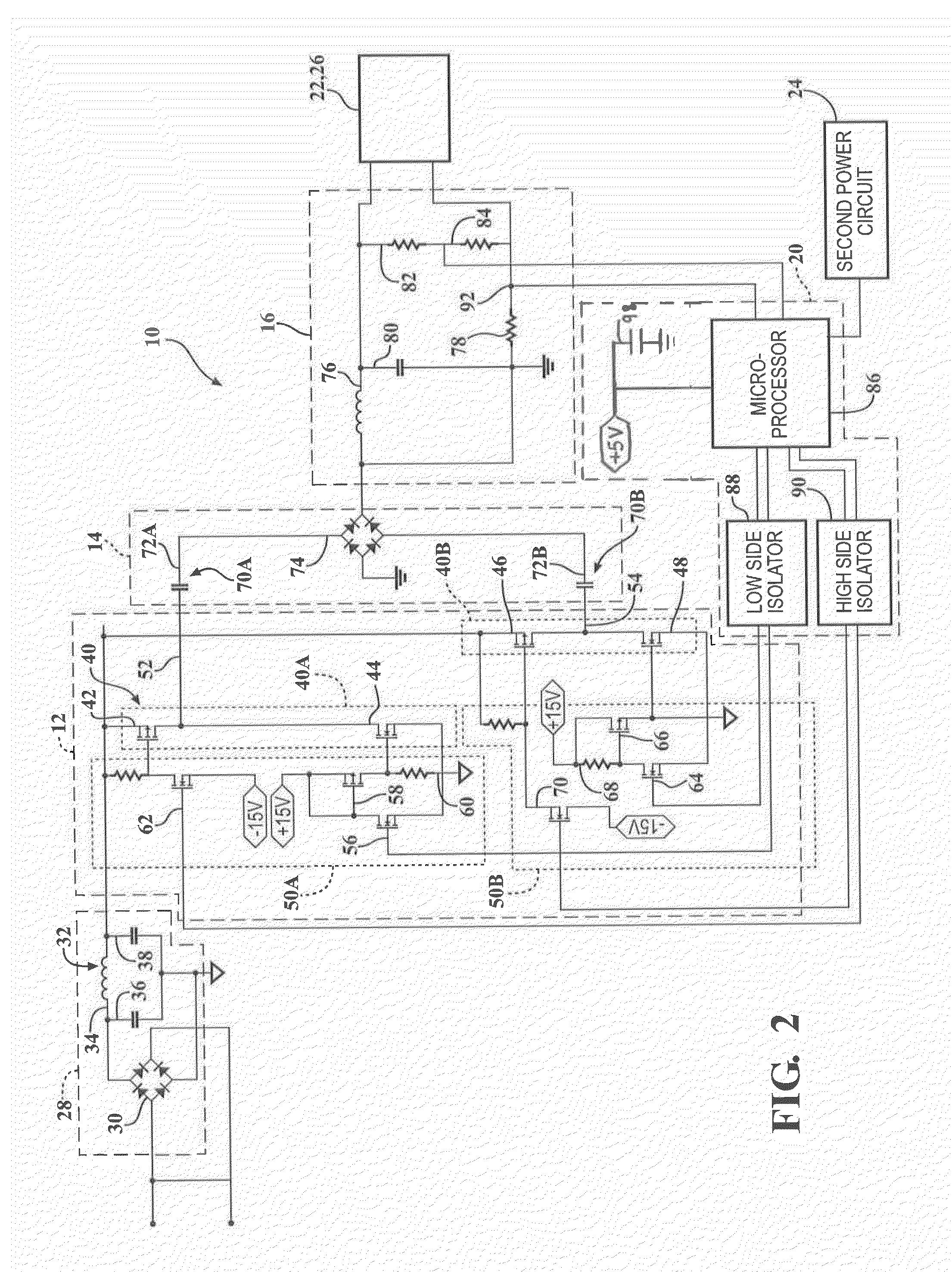
[0055]Referring to the Figures, wherein like numerals indicate like or corresponding parts throughout the several views, a power device 2 having a first power circuit 10 is provided. As shown in FIG. 1, the first power circuit 10 includes a switching device 12, a frequency dependent reactive device 14 and an output section 16.

[0056]The first power circuit 10 may be used to convert the power provided by a source of electrical power of a first type to electrical power of a more desirable type. For example, the first power circuit 10 may be used to convert electrical power received from a source of electrical power 18, such as a power grid. The source of electrical power 18 may be provided as an alternating current at a given voltage, e.g., 120 volts at a frequency of 60 Hertz (the North American Standard) or 220-240 volts at a frequency of 50 Hz (the European Standard) to a more desirable voltage. The acceptable input voltage range for the invention is a low of 85 volts to a high of 3...


PUM


Abstract

An energy efficient apparatus includes a switching device, a frequency dependent reactive device, and a control element is provided. The switching device is coupled to a source of electrical power and includes a pair of transistors and is adapted to receive a control signal and to produce an alternating current power signal. The frequency of the alternating current power signal is responsive to the control signal. The frequency dependent reactive device is electrically coupled to the pair of transistors for receiving the alternating current power signal and producing an output power signal. The frequency dependent reactive device is chosen to achieve a desired voltage of the output power signal relative to the frequency of the alternating current power signal. The control element senses an actual voltage of the direct current power signal and modifies the control signal delivered to achieve the desired voltage of the direct current power signal.

Description

CROSS-REFERENCE TO RELATED APPLICATION[0001]This application is a continuation of prior U.S. patent application Ser. No. 13 / 588,262, filed Aug. 17, 2012, the disclosure of which is hereby incorporated by reference in its entirety.FIELD OF THE INVENTION[0002]The present invention relates generally to power device circuits, and more particularly, to a power circuit which transforms electrical power utilizing a frequency dependent reactive device.BACKGROUND OF THE INVENTION[0003]The Energy Crises Requires Demand Side Response That Lowers Current Loads. The Energy Crisis is upon us worldwide. For instance, the U.S. Department of Energy predicts that by 2015 there will not, on the average, be enough electric power to supply average demand in the U.S.[0004]One of the controllable offenders is “Vampire Loads”. Also call “Wall Wort Power” or “Standby Power” this electricity waste makes up a large portion of homes' or offices' miscellaneous electric load and is a large waste of power. Vampir...

Claims


Application Information

Patent Timeline
Patent Type & Authority Patents(United States)
IPC IPC(8): H02M5/458H02M7/48H02M3/335H02M7/217H02M1/00H05B44/00
CPCH02M7/48H02M3/33507H02M7/217Y10T307/406H02M2001/0019H05B45/3725H02M1/0019H02M7/2176H02M7/155H02J7/00H02M1/0009H02M5/458H02M1/36H02M1/08
Inventor FREEMAN, MICHAEL H.WEAVER, JR., W. J. "JIM"FREEMAN, MITCHAEL C.DIETER, ROBERTSANTEE, BRIAN
Owner SMART PRONG TECH INC
Why Eureka
Try Eureka