Shock absorber

a technology of shock absorber and shock absorber, which is applied in the direction of shock absorber, mechanical equipment, transportation and packaging, etc., can solve the problem of unstable damage for

Active Publication Date: 2012-03-29
HITACHI ASTEMO LTD
View PDF6 Cites 35 Cited by
  • Summary
  • Abstract
  • Description
  • Claims
  • Application Information

AI Technical Summary

Benefits of technology

[0004]An object of the present invention is to provide a shock ab

Problems solved by technology

In a shock absorber having a reservoir as stated above, if the gas in the reservoir gets mixed into the hydraulic oil as

Method used


Image

  • Shock absorber
  • Shock absorber
  • Shock absorber

Examples


first embodiment

[0021]the present invention will be explained with reference to FIGS. 1 to 5.

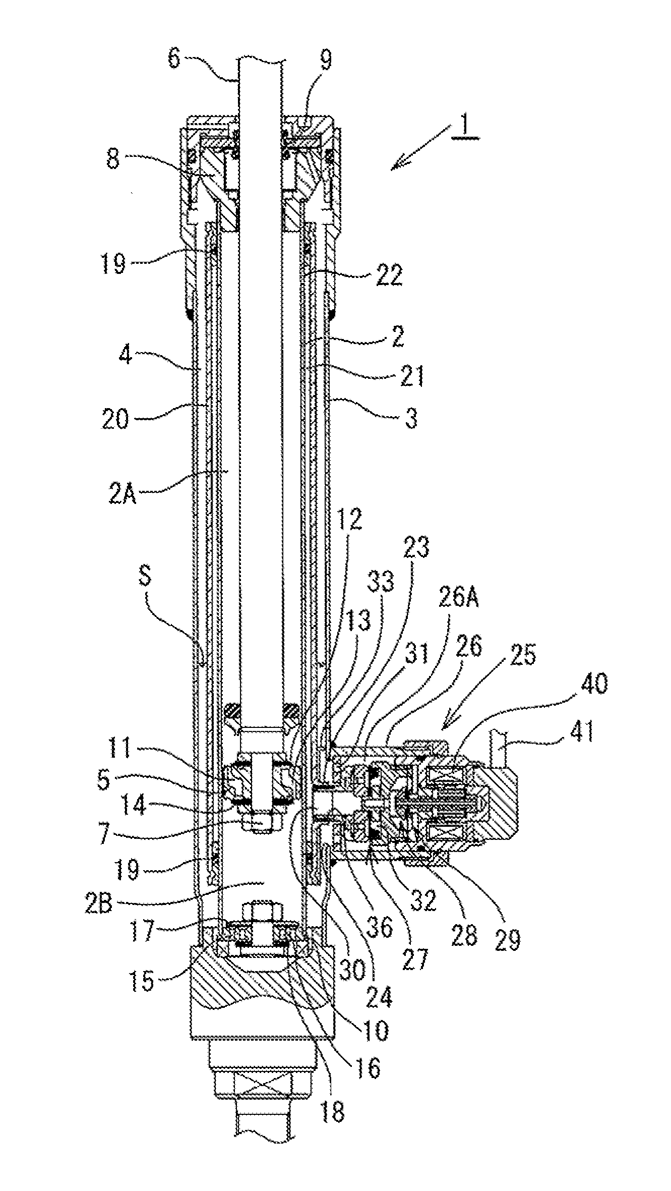
[0022]As shown in FIGS. 1 and 2, a shock absorber 1 according to this embodiment is a tube-type damping force control hydraulic shock absorber having a double-tube structure comprising a cylinder 2 and an outer tube 3 provided around the outer periphery of the cylinder 2. An annular reservoir 4 is formed between the cylinder 2 and the outer tube 3. A piston 5 is slidably fitted in the cylinder 2. The piston 5 divides the interior of the cylinder 2 into two chambers, i.e. a cylinder upper chamber 2A and a cylinder lower chamber 2B. The piston 5 is connected with one end of a piston rod 6 by a nut 7. The other end of the piston rod 6 extends through the cylinder upper chamber 2A and through a rod guide 8 and an oil seal 9, which are provided in the upper end of the double-tube structure comprising the cylinder 2 and the outer tube 3. The other end of the piston rod 6 extends to the outside of the cylinder 2. ...


PUM


Abstract

A flow of hydraulic oil induced by sliding movement of a piston in a cylinder is controlled by a pilot-type main valve and a pilot valve, which is a pressure control valve, to generate a damping force. The pilot valve is adjusted in its valve-opening pressure with the thrust of a solenoid and adjusts the pressure in a back pressure chamber to control the valve-opening pressure of the main valve. A baffle plate is provided in a reservoir to isolate from each other the surface of hydraulic oil in the reservoir and an inlet port through which the hydraulic oil flows into the reservoir from a damping force generating mechanism, thereby suppressing the occurrence of aeration and cavitation. The baffle plate is secured by inserting a connecting port through a positioning opening and holding a separator tube with a pair of arm portions.

Description

BACKGROUND OF THE INVENTION[0001]The present invention relates to shock absorbers that generate a damping force by controlling the flow of a hydraulic fluid in relation to the stroke of a piston rod.[0002]Cylinder type hydraulic shock absorbers attached to suspension systems of vehicles, for example, automobiles, are generally arranged as follows. A piston connected with a piston rod is inserted in a cylinder having a hydraulic oil therein as a hydraulic fluid. A stroke of the piston rod causes sliding movement of the piston in the cylinder, which in turn induces a flow of hydraulic oil. The hydraulic oil flow is controlled by a damping force generating mechanism, which comprises an orifice, a disk valve, etc., to generate a damping force. In some shock absorbers of this type, a reservoir having the hydraulic oil and a gas sealed therein is connected to the cylinder to compensate for a cubic capacity change in the cylinder caused by the entry and exiting of the piston rod into and f...

Claims


Application Information

Patent Timeline
IPC IPC(8): F16F9/06F16F9/50F16F9/16
CPCB60G17/08F16F9/34F16F9/46F16F9/48F16F2226/04F16F9/18F16F9/32F16F9/325F16F9/465F16F9/50
Inventor YAMASAKI, JINKAGAWA, SHINICHIYOSHIDA, TETSUO
Owner HITACHI ASTEMO LTD
Why Eureka
Try Eureka