Conveyor chain

a conveyor chain and conveyor technology, applied in conveyor parts, transportation and packaging, rollers, etc., can solve the problems of prior art magnet-equipped chains, inability to steadily convey articles m, other difficulties, etc., to prevent the magnet piece from escaping, prevent the magnet piece from being damaged, and reliably fix the magnet piece

Active Publication Date: 2012-03-29
TSUBAKIMOTO CHAIN CO
View PDF12 Cites 15 Cited by
  • Summary
  • Abstract
  • Description
  • Claims
  • Application Information

AI Technical Summary

Benefits of technology

[0023]Then, because the magnet pieces insertably stored in the magnet storing blind holes of the synthetic resin link modules are closed by the link side surfaces of the synthetic resin link module adjacently disposed in the chain width direction, the link side surface of the adjacently disposed synthetic resin link module covers the opening of the magnet storing blind hole and stops the magnet piece from escaping. Then, it becomes possible to reliably prevent the magnet piece from escaping even if vibrations occur up and down and right and left directions during the conveyance of the articles. Thus, the aspects of the invention described herein prevent sudden damage to the magnet piece that otherwise could come into contact with peripheral devices. Hence, aspects of the invention provide the ability to reliably fix the magnet piece without separately requiring a fixing means for fixing the magnet piece such as those used in the prior art magnet-equipped chain.
[0024]Still more, because the magnet piece is stored in the synthetic resin link module, it becomes possible to convey the articles upward stably without a slip even if a component force in a slope direction acting on the articles while conveying on the slope exceeds a frictional force or even if a slippery liquid such soapy water, lubricant oil and others spreads on the synthetic resin link module, causing the loading surface of the loading portion to be excessively slippery.
[0025]Still more, it becomes possible to realize a smooth driving and conveyance by fully assuring a slack by using an intermediate roller, i.e., an idler roller and the like, that absorbs elongation of the chain on the chain return side to avoid an increase of a radius, i.e., a so-called ‘backbend radius’ bending in a direction opposite from the conveyor surface, that occurs when a magnet piece is mounted on an outer peripheral surface of a prior art synthetic resin link module.
[0026]According to the second aspect of the conveyor chain of the invention, because the plurality of synthetic resin link modules composing the link row comprise at least the magnetism generating link modules storing the magnet pieces and the driving link module storing

Problems solved by technology

One problem with each of the conveyer chain shown in FIG. 11, however, is that because the link module 510 for loading the articles M on the loading portion 511 is molded of synthetic resin to exhibit a self-lubricant properties, there is a problem in that it is unable to steadily convey the articles M because they may suddenly fall or slip when a shock is made a conveyor surface or when a component force in a slope direction acting on the articles M exceeds a frictional force of conveying the articles M on a slope, as shown in FIG. 12.
Additionally, when a slippery liquid such as soapy water, lubricant oil or others spreads on the link module 510 and the loading surface of the loading portion 511 for loading the articles M of the link module 510 is excessively slippery, there may be other difficulties.
The prior art magnet-equipped chain also problems.
The chain also causes such problems for device design that it hinders in dimensioning layouts of a chain guide, driving sprocket and others and that a chain turning radius increases excessively in conveying while turning horizontally.
If the chain base portion is narrowed along with the projecting parts of the attracting magnetic units to solve the abovementioned problems, there arises another problem that chain strength is remarkably weakened.
As a result, it becomes unable to f

Method used


Image

  • Conveyor chain
  • Conveyor chain
  • Conveyor chain

Examples


first embodiment

[0041]A first embodiment of a conveyor chain of the invention will be explained below with reference to the drawings.

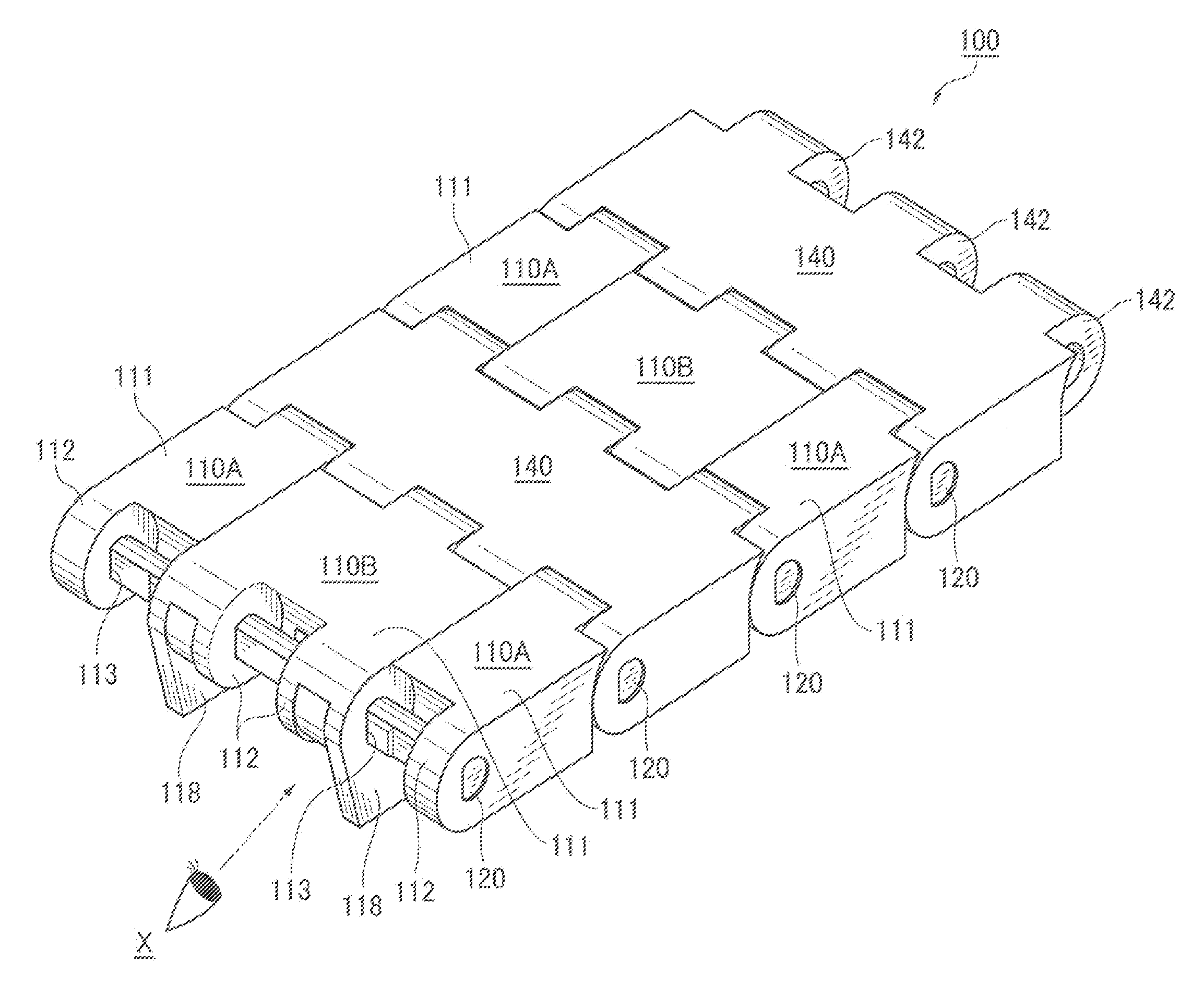
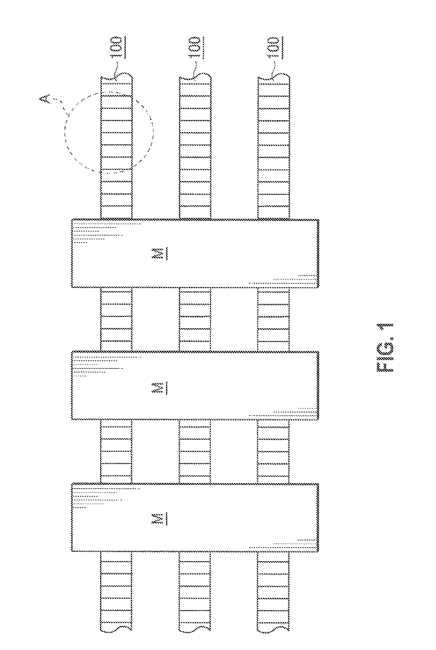
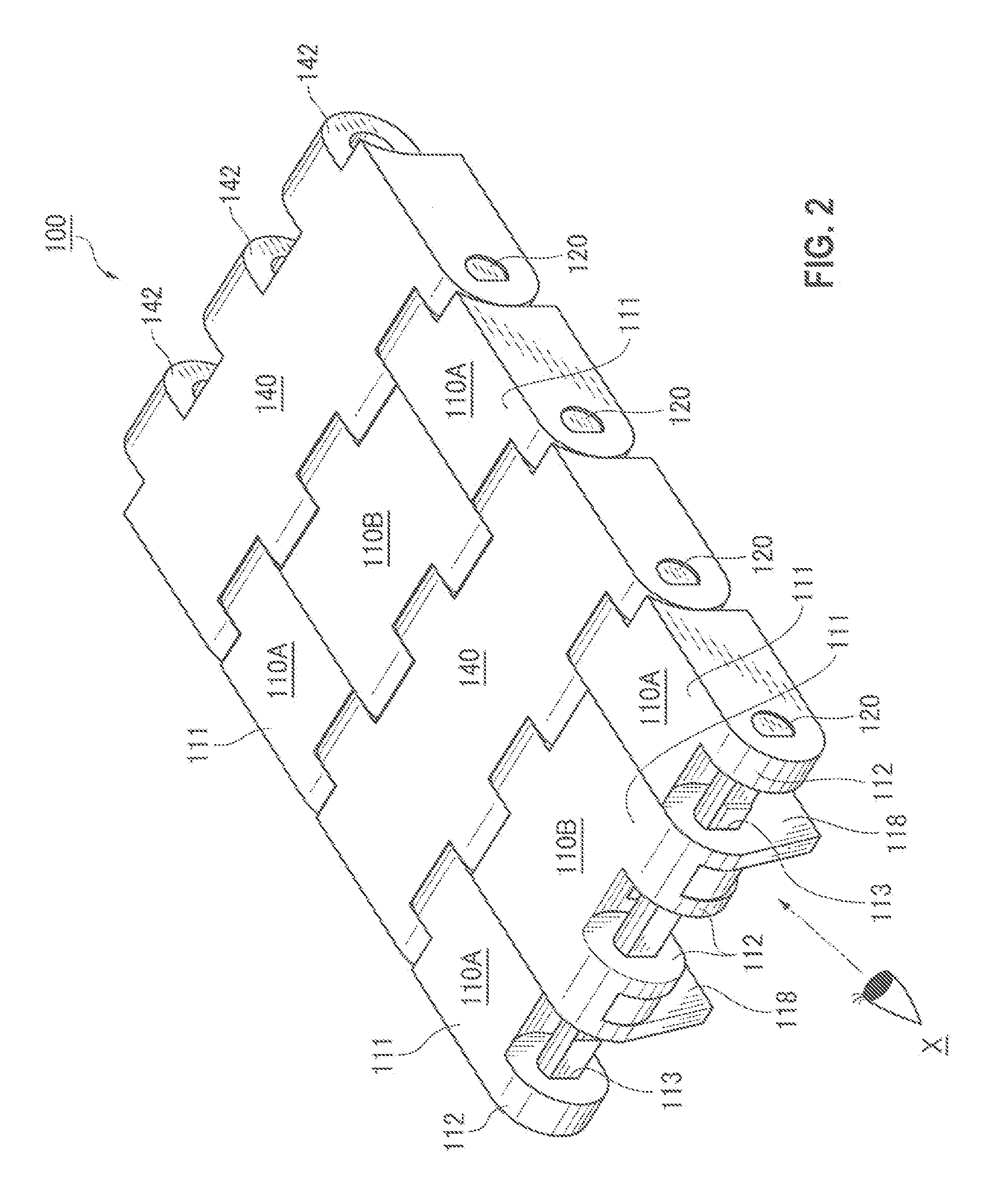
[0042]Here, FIG. 1 is a schematic diagram showing a mode of use of a conveyor chain of a first embodiment of the invention, FIG. 2 is an enlarged view of a part A of the conveyor chain of the first embodiment shown in FIG. 1, FIG. 3 is an assembly exploded view of the conveyor chain of the first embodiment of the invention, FIG. 4 is a perspective view of the conveyor chain seen from a view point X on the back of the chain shown in FIG. 2, FIG. 5 is a side view seen from a magnet piece inserting side of a magnetism generating link module shown in FIG. 2, FIG. 6 is a front view of the conveyor chain shown in FIG. 2, FIG. 7 is an operational view of the conveyor chain shown in FIG. 1 in conveying articles on a slope, FIG. 8 is an assembly exploded view of a conveyor chain of a second embodiment of the invention, FIG. 9 is an assembly exploded view of a conveyor chain of...

second embodiment

[0072]A conveyor chain 200 of a second embodiment of the invention will be explained next with reference to FIG. 8.

[0073]Similarly to the conveyor chain 100 shown in FIG. 1, the conveyor chains 200 as shown in FIG. 8 are also arrayed respectively in parallel in the line width direction of the conveyor line and convey articles M which are long in the conveying line width direction upward on a slope.

[0074]That is, as shown in FIG. 8, the conveyor chain 200 of the second embodiment of the invention comprises a plurality of synthetic resin link modules 210 each having a loading portion 211 for loading the articles M and hinge portions 212 projecting from the front and rear parts of the loading portion 211. The conveyor chain is constructed by linking the large number of synthetic resin link modules in the chain longitudinal direction in a predetermined array pattern by inserting link pins 220 through pin inserting holes 213 formed through the hinge portions 212 of these synthetic resin ...

third embodiment

[0080]a conveyor chain 300 of a third embodiment of the invention will be explained next with reference to FIG. 9.

[0081]Similarly to the conveyor chain 100 shown in FIG. 1, the conveyor chains 300 as shown in FIG. 9 are also arrayed respectively in parallel in the line width direction of the conveyor line and convey specifically long articles M which are long in the conveying line width direction upward on a slope.

[0082]That is, as shown in FIG. 9, the conveyor chain 300 of the third embodiment of the invention provided respectively in the conveyor line comprises a plurality of synthetic resin link modules 310 each having a loading portion 311 for loading the articles M and hinge portions 312 projecting from the front and rear parts of the loading portion 311. The conveyor chain is constructed by linking the large number of synthetic resin link modules in the chain longitudinal direction in a predetermined array pattern by inserting link pins 320 through pin inserting holes 313 form...


PUM


Abstract

A conveyor chain that enables magnet pieces for attracting and retaining articles conveyed on the chain. The magnet pieces are incorporated into synthetic resin link modules without changing a predetermined chain width and dimensioning of other device components. A large number of link rows consisting of a number of synthetic resin link modules are connected together so as to have a predetermined chain width W. At least some of the synthetic resin link modules have magnet storing blind holes which open in the chain width direction from link side surfaces such that a magnet piece can be insertably stored in the magnet storing blind hole and securely enclosed by the link side surface of an adjacent synthetic resin link module in the chain width direction.

Description

CROSS REFERENCE TO RELATED APPLICATIONS[0001]This application claims the foreign priority benefit under Title 35, United States Code, §119 (a)-(d) of Japanese Patent Application No. 2010-217601, filed on Sep. 28, 2010 in the Japan Patent Office, the disclosure of which is herein incorporated by reference in its entirety.BACKGROUND OF THE INVENTION[0002]1. Field of the Invention[0003]The present invention relates to a conveyor chain for loading and conveying articles and more specifically to a conveyor chain for loading and conveying the articles by magnetically attracting and retaining them even when a conveying surface is sloped or slippery.[0004]2. Related Art[0005]One example of a conveyor chain that is currently used in the art is the conveyor belt 500 shown in FIG. 11. The conveyor belt 500 has link rows each having a predetermined chain width W and composed of link modules 510. The link modules 510 include a loading portion 511 for loading articles M (referred to simply as ‘co...

Claims


Application Information

Patent Timeline
IPC IPC(8): B65G17/46
CPCB65G17/46B65G17/08
Inventor OZAKI, HAJIMEOTA, KEIKO
Owner TSUBAKIMOTO CHAIN CO
Why Eureka
Try Eureka