Control system and control method of an in-vehicle solar energy charger

a solar energy charger and control system technology, applied in the direction of secondary cell servicing/maintenance, light to electrical conversion, electrochemical generators, etc., can solve the problems of insufficient flexibility of the control system and low utilization of solar energy, and achieve the effect of maximizing the output of solar energy

Active Publication Date: 2012-03-29
BYD CO LTD
View PDF3 Cites 19 Cited by
  • Summary
  • Abstract
  • Description
  • Claims
  • Application Information

AI Technical Summary

Benefits of technology

[0050]Referring to the control system and control method of the in-vehicle solar energy charger of the present invention, the controller may perform the maximum photovoltaic power tracking algorithm and control the output power of the solar energy charger to charge the power battery or starting battery, according to the input power of the solar energy charger. Thus, there is no need to replace hardware. Only the control process may be replaced. As a result, the control system for an in-vehicle solar energy charger and the control method are flexible and can realize the maximum output of solar energy.

Problems solved by technology

Therefore, concerning the control method of the analog device, the control system is not flexible enough and the utilization of the solar energy is not high.

Method used


Image

  • Control system and control method of an in-vehicle solar energy charger
  • Control system and control method of an in-vehicle solar energy charger
  • Control system and control method of an in-vehicle solar energy charger

Examples


Embodiment Construction

[0054]Reference will be made in detail to embodiments of the present invention. The embodiments described herein according to drawings are explanatory, illustrative, and used to generally understand the present invention. The embodiments shall not be construed to limit the present invention. The same or similar elements and the elements having same or similar functions are denoted by like reference numerals throughout the descriptions.

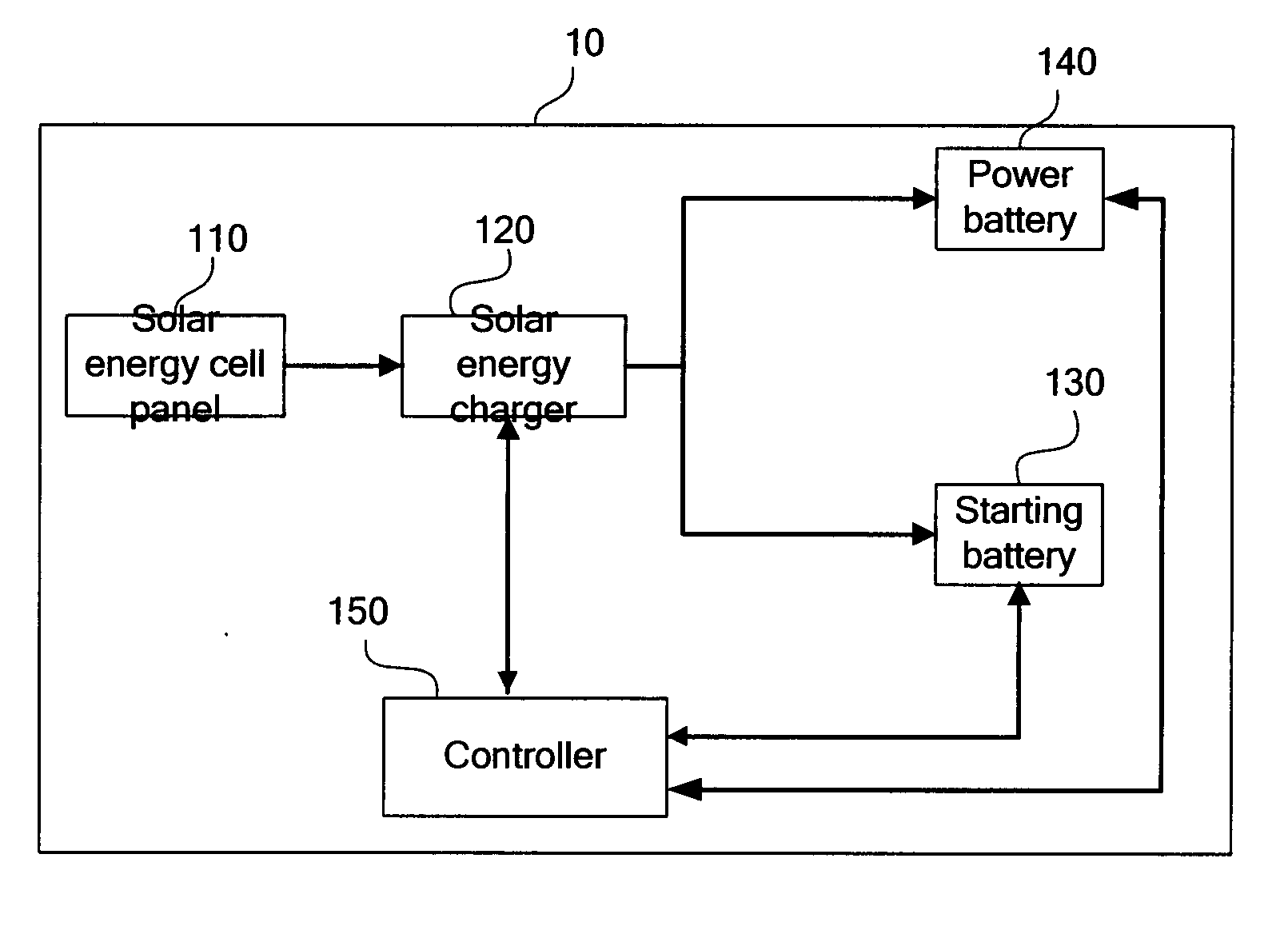
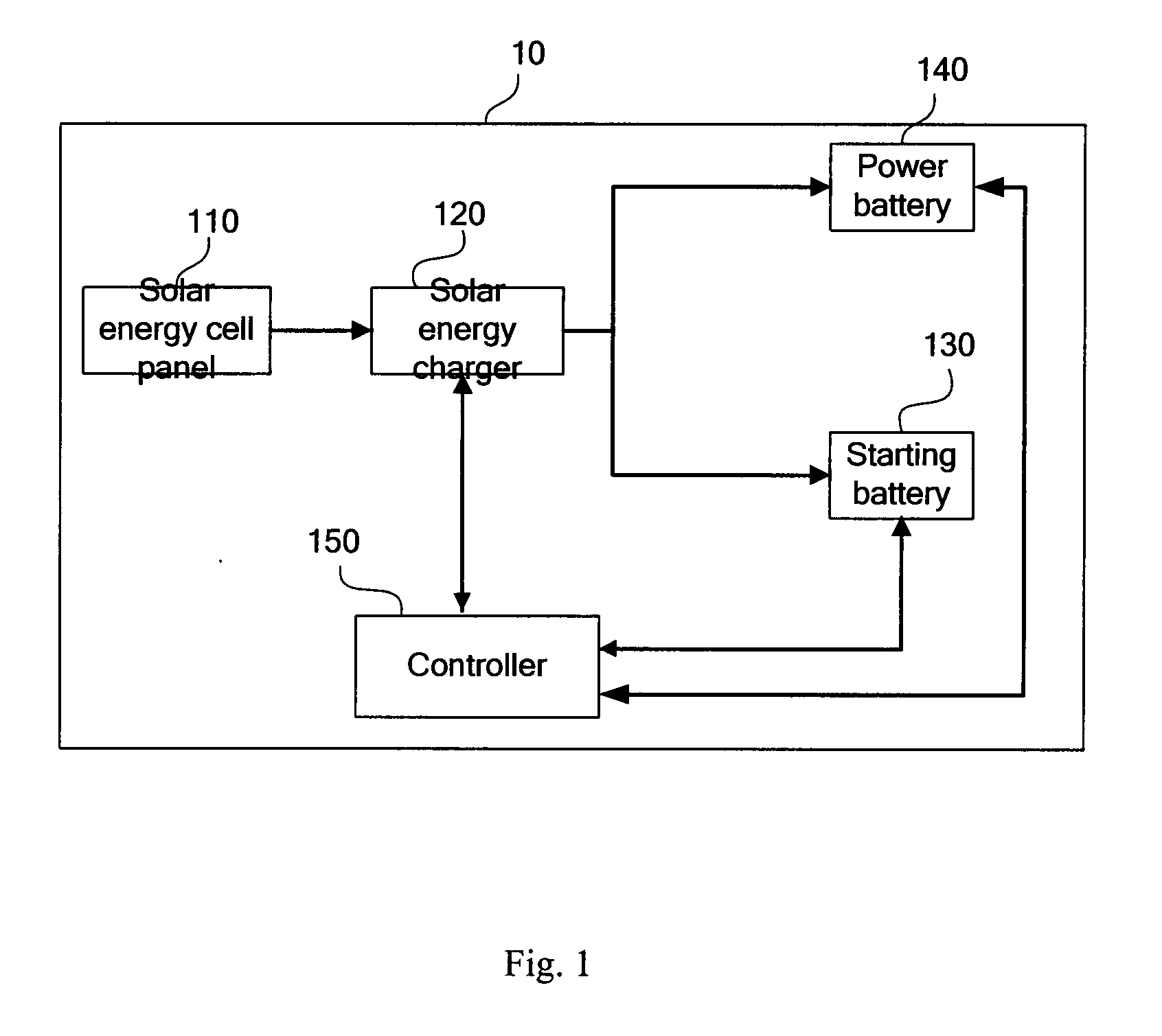
[0055]As shown in FIG. 1, an embodiment of the present invention provides a control system 10 of an in-vehicle solar energy charger comprising a solar cell panel 110, a solar energy charger 120, a starting battery 130 and a power battery 140. The solar cell panel 110 is electrically connected to the solar energy charger 120. The starting battery 130 and the power battery 140 are electrically connected to the solar energy charger 120 respectively, in which, the control system of the in-vehicle solar energy charger further comprises a controller 150. The...


PUM

PropertyMeasurementUnit
voltageaaaaaaaaaa
poweraaaaaaaaaa
output poweraaaaaaaaaa

Abstract

A control system for an in-vehicle solar energy charger, comprising a solar cell panel, a solar energy charger, a starting battery, a power battery and a controller. The solar energy charger, the starting battery and the power battery are electrically connected to the controller respectively. The controller is configured for performing a maximum photovoltaic power tracking algorithm and controlling an output power of the solar energy charger for charging the power battery or starting battery, according to an input power of the solar energy charger.

Description

CROSS-REFERENCE TO RELATED APPLICATIONS[0001]The present application claims priority to and benefits of Chinese Patent Application No. 201010293257.2 filed with State Intellectual Property Office of China on Sep. 27, 2010, the entirety of which is hereby incorporated by reference.BACKGROUND[0002]1. Technical Field[0003]The present invention relates to a control system and a control method of an in-vehicle solar energy charger.[0004]2. Description of the Related Art[0005]As it is widely known, a running mileage of an electric vehicle is a very important feature. A power source of the electric vehicle is mainly an in-vehicle power battery. Only if the voltage of the in-vehicle power battery is sufficient, normal operation of the electric vehicle may be ensured. Solar energy has become a new green energy to which people pay more and more attentions. The running mileage of the electric vehicle may be improved due to the application of the solar energy to the electric vehicle.[0006]Refer...

Claims


Application Information

Patent Timeline
Patent Type & Authority Applications(United States)
IPC IPC(8): H01M10/46
CPCY02T10/7005B60L8/003B60L11/1809Y02T90/14Y02T10/7094Y02T10/7083H02J7/04B60L53/00H02J7/007Y02T10/70Y02T10/7072
Inventor WU, ZHENJIESHEN, XIAOFENGZHANG, JIANHUA
Owner BYD CO LTD
Why Eureka
Try Eureka