System and Method for Controlling Output of a Battery Pack

a battery pack and output technology, applied in cell components, safety/protection circuits, instruments, etc., can solve the problems of battery pack current sinking and/or sourcing limits, limited degradation of battery packs, etc., to reduce the possibility of battery pack degradation, reduce the possibility of contactor opening, and reduce the effect of intervening in drive operation

Active Publication Date: 2012-03-29
A123 SYSTEMS LLC
View PDF4 Cites 40 Cited by
  • Summary
  • Abstract
  • Description
  • Claims
  • Application Information

AI Technical Summary

Benefits of technology

[0005]By opening a contractor that electrically couples a battery pack to a circuit that is external to the battery pack when an integrated amount of current of the battery pack exceeds a threshold level, it is possible to reduce the possibility of battery pack degradation without having to access the battery pack and replace a fuse. In particular, a contactor can be controlled in response to an output of a current sensor. For example, during periods when a battery is operating within prescribed limits the contactor can be controlled in response to requests to operate a vehicle. However, if the current entering or exiting the battery exceeds a threshold amount of current, the amount of current exceeding the threshold may be integrated. When the value of the integrated current exceeds a threshold the contactor may be opened. In this way, current flow into and out of a battery pack may be controlled without having to rely on a hardware fuse or an external controller. Further, the approach correlates the degree of over-current operation to the duration of that condition, in that current may be allowed to go slightly over limit for a long duration before opening the contactors, whereas current may be allowed to go significantly over limit for only a short duration before opening the contactors. In this way, it is possible to take advantage of the interrelationship between the degree and duration of over-current operation. Such an approach can reduce unnecessary contactor opening and thereby reduce intervening in drive operation. As some applications may be more prone to longer, but lower, over current conditions, while other applications may be more prone to shorter, but higher, over current conditions, the above approach accommodates both conditions and various combinations therebetween.
[0006]The present description may provide several advantages. In particular, the method can reduce battery pack degradation without having to replace hardware or rely on external systems. Further, the present description provides for additional measures of battery pack degradation protection. Further still, the level of threshold currents can be adjusted for different capacity battery packs without having to change hardware or software. Further still, the level of threshold currents may be changed dynamically with battery temperature, charge level, or age.

Problems solved by technology

A battery pack may source or sink current during operation, where the amount of current may be limited due to various constraints.
In addition, the battery pack current sinking and / or sourcing limits may be imposed via hardware.
Thus, degradation of a battery pack may be limited by way of a combination of hardware and software.
However, accessing the battery pack to replace a blown fuse can be cumbersome.
Furthermore, a load or source external to the battery pack may not have the capacity to precisely follow battery limits as desired during periods of degradation, or during transient operation.

Method used


Image

  • System and Method for Controlling Output of a Battery Pack
  • System and Method for Controlling Output of a Battery Pack
  • System and Method for Controlling Output of a Battery Pack

Examples


Embodiment Construction

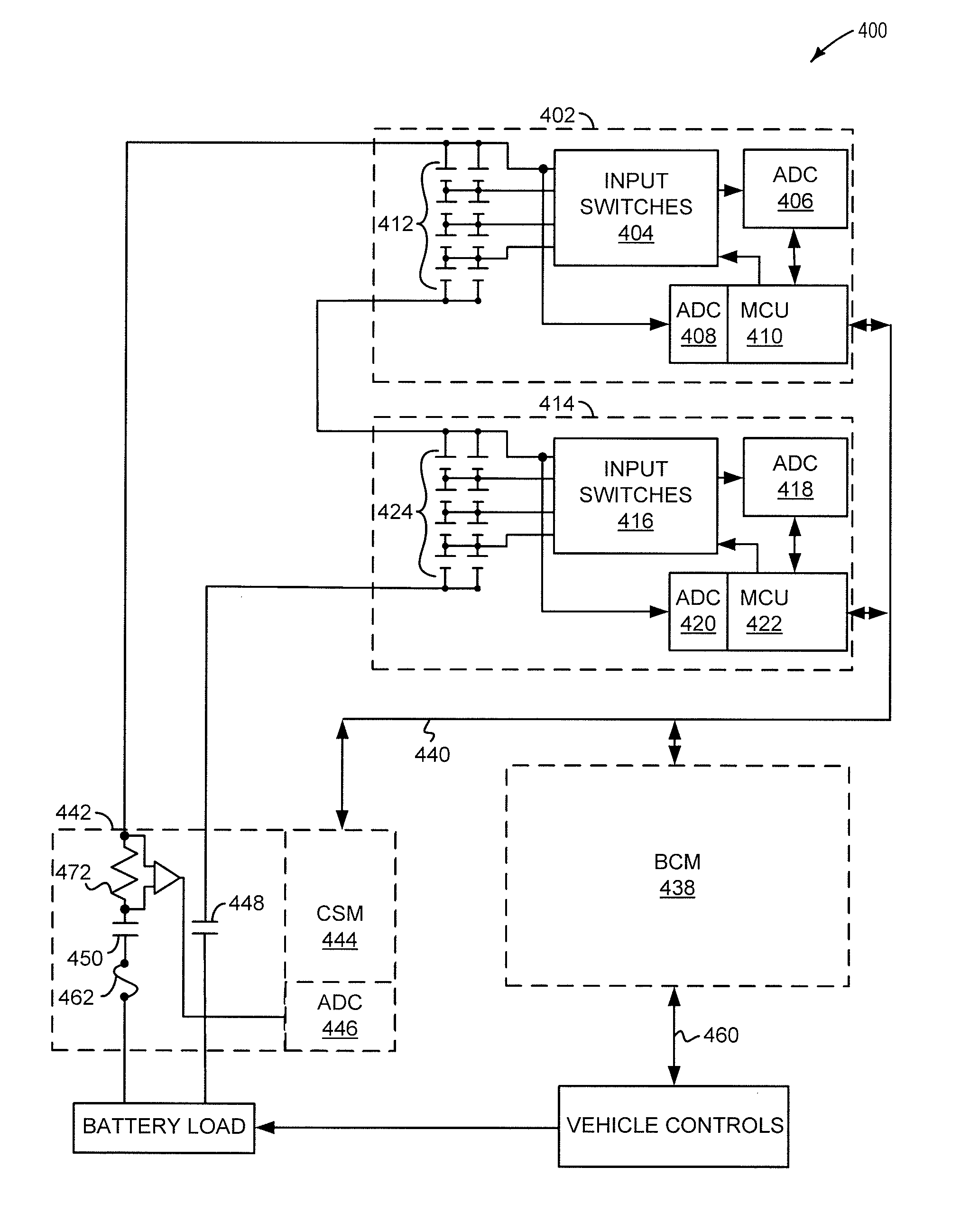
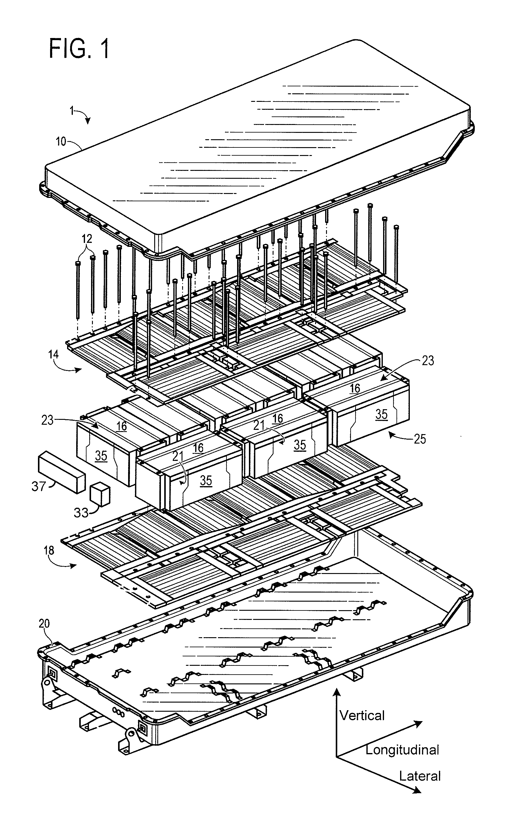
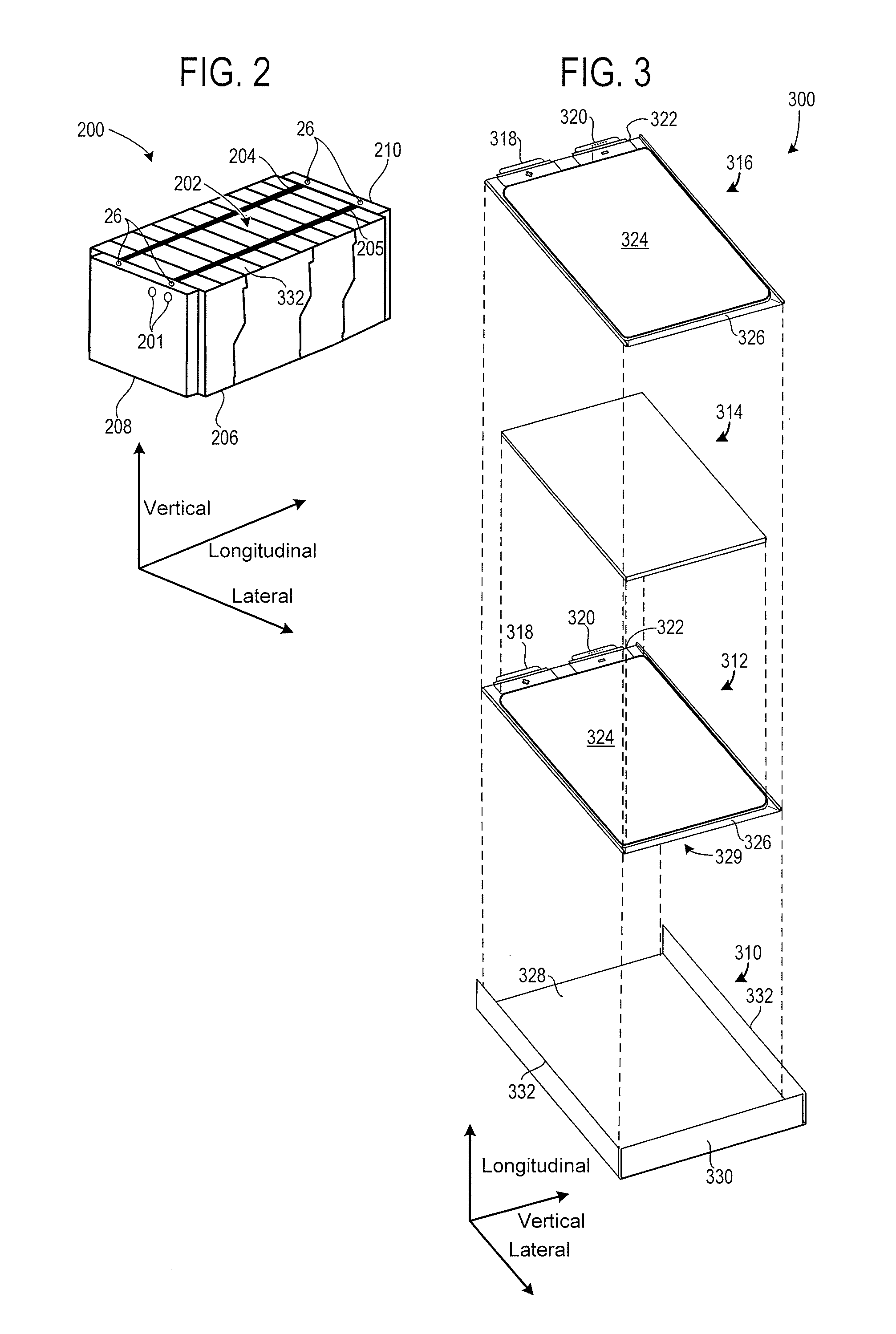
[0014]The present description is related to controlling the output of a battery pack. In one embodiment, battery cells such as those illustrated in FIGS. 2-3 may be combined in a battery pack as illustrated in FIG. 1. The power from the battery cells of FIGS. 1-3 may be selectively delivered to a load external to the battery pack via a contactor as shown in FIG. 4. In one example illustrated by the method of FIG. 5, a battery pack output of the system of FIG. 4 is decoupled from a load or source when current entering or exiting the battery pack exceeds a threshold level or amount.

[0015]FIG. 1 shows an exploded view of a battery assembly 1. The battery assembly may include a cover 10, coupling devices 12, a first cooling subsystem 14 (e.g., cold plate), a plurality of battery modules 16, a second cooling subsystem 18 (e.g., cold plate), and a tray 20. The cover may be attached to the tray via a suitable coupling device (e.g., bolts, adhesive, etc.,) to form a housing surrounding the ...


PUM

PropertyMeasurementUnit
voltageaaaaaaaaaa
currentaaaaaaaaaa
voltageaaaaaaaaaa

Abstract

Systems and methods for controlling the output of a battery pack are disclosed. In one example, a battery pack contactor is opened in response to battery pack current. The system and method may reduce battery pack degradation and increase system flexibility.

Description

CROSS REFERENCE TO RELATED APPLICATIONS[0001]This application claims priority from U.S. Provisional Patent Application Ser. No. 61 / 185,763, filed Jun. 10, 2009 and entitled ROBUST LIMIT BATTERY FUSE, the entirety of which is hereby incorporated herein by reference for all intents and purposes.TECHNICAL FIELD[0002]The present description relates to controlling output of a battery pack. In one example, the battery pack provides power to a vehicle.BACKGROUND AND SUMMARY[0003]A battery pack may source or sink current during operation, where the amount of current may be limited due to various constraints. In order to stay within the battery pack limits, the battery pack may transmit the battery pack souring and / or sinking capacities to an external controller so that the external load or source that is in communication with the battery pack may adjust operation of the load or source to accommodate the battery pack limits. In addition, the battery pack current sinking and / or sourcing limit...

Claims


Application Information

Patent Timeline
Patent Type & Authority Applications(United States)
IPC IPC(8): H02J7/00H01M50/528
CPCG01R31/3658H02J7/0031H01M10/48H01M10/44G01R31/396Y02E60/10G01R31/36H02J7/00H02J7/00036H01M50/528H01M10/0525H01M10/441
Inventor RUTKOWSKI, BRIAN D.MOORHEAD, BRIAN C.
Owner A123 SYSTEMS LLC
Why Eureka
Try Eureka