Directable magnetic mount for light emitter, a light source, a base and an illumination system

a technology of magnetic mount and light emitter, which is applied in the direction of lighting support devices, lighting and heating apparatus, coupling device connections, etc., can solve the problems of relatively bulky light sources, relatively large heat generation, and inability to direct light sources, and achieve the effect of sufficient cooling

a technology of magnetic mount and light emitter, which is applied in the direction of lighting support devices, lighting and heating apparatus, coupling device connections, etc., can solve the problems of relatively bulky light sources, relatively large heat generation, and inability to direct light sources, and achieve the effect of sufficient cooling

US20120075857A1Active Publication Date: 2012-03-29KONINKLIJKE PHILIPS ELECTRONICS NV

Image

  • Directable magnetic mount for light emitter, a light source, a base and an illumination system
  • Directable magnetic mount for light emitter, a light source, a base and an illumination system
  • Directable magnetic mount for light emitter, a light source, a base and an illumination system

Examples


Embodiment Construction

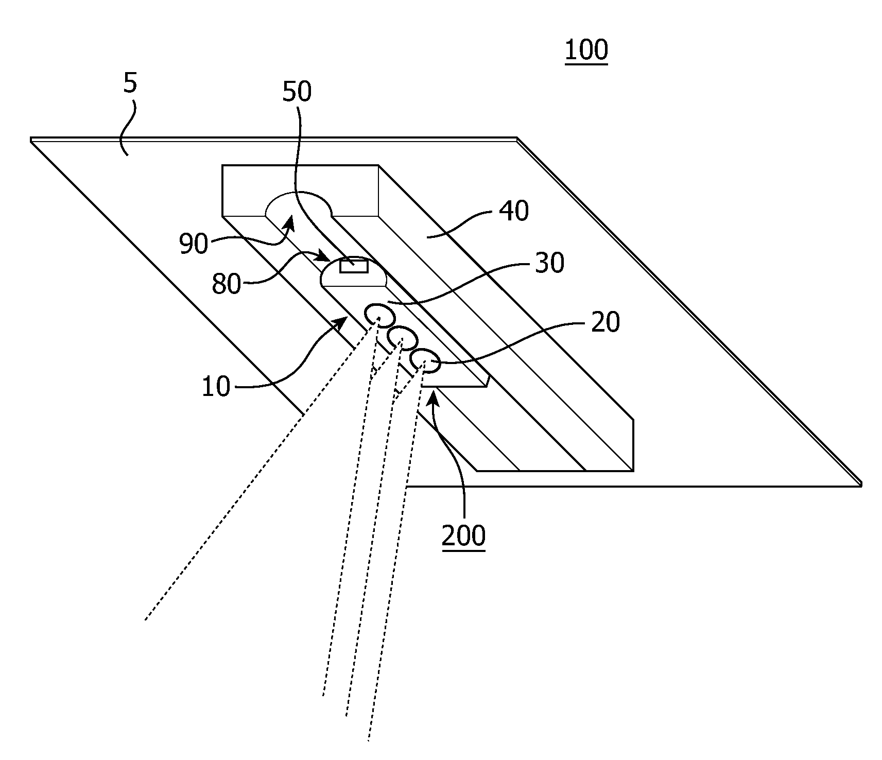
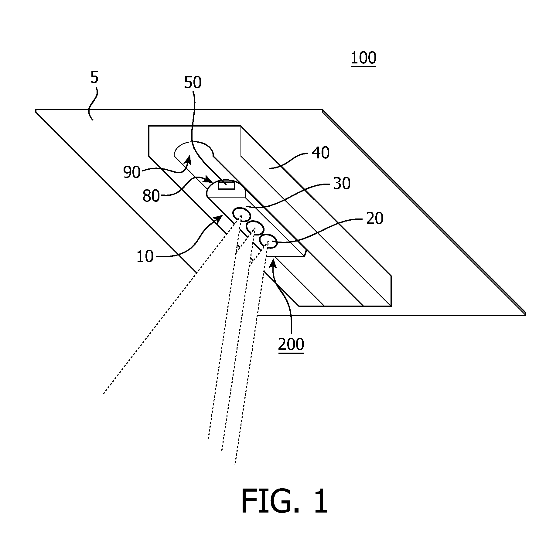
[0058]FIG. 1 shows a plan-view of an illumination system 100 comprising a light source 200 including a directable magnetic mount 10 comprising a light emitter 20 arranged in a base 40 constituted by a heat sink 40. The base 40 is connected to a surface 5 which may, for example, be a wall 5, a ceiling 5, or any other surface 5 against which the illumination system 100 may be connected. In the embodiment shown in FIG. 1 part of the outer wall 90 of the heat sink 40 comprises a substantially cylindrical indentation 90. The light source 200 comprises interface means 30 partially having a shape of a cylinder having substantially the same radius as the cylindrical indentation 90 of the heat sink 40. Furthermore, the interface means 30 comprises material capable of conducting thermal energy away from the light emitter 20. Due to the fact that the at least part of the outer wall 80 of the interface means 30 comprises the cylindrical shape matching the cylindrical indentation 90 of the heat ...


PUM


Abstract

The invention relates to a directable magnetic mount (10) for a light emitter (20). The invention also relates to a light source (200), to a base (40) and to an illumination system (100). The directable magnetic mount comprises interface means (30) configured for conducting thermal energy away from the light emitter to a heat sink (40), and comprises a magnetic connector (50) configured for magnetically connecting the directable magnetic mount to the base. The magnetic connector is configured for thermally interconnecting the interface means and the heat sink. The interface means is configured for being thermally connected to the heat sink at a plurality of orientations of the interface means with respect to the heat sink. Each of the plurality of orientations of the interface means comprises a different emission direction of the light emitter.The effect of the measures according to the invention is that it enables to omit the need for a heat sink in the light source which enables to reduce the size of the light source while also allowing to reposition and redirect the light emitted from the illumination system.

Description

FIELD OF THE INVENTION[0001]The invention relates to a directable magnetic mount for a light emitter.[0002]The invention also relates to a light source, a base and an illumination system comprising a light source and the base.BACKGROUND OF THE INVENTION[0003]Light emitters are known per se and are used in every realm of daily life. They are, inter alia, used in general illumination systems, for example, for illuminating indoor and / or outdoor environments, homes, shops, factories and offices, but also, for example, in vehicles of any kind. Also in different application areas, such as in image projection systems, light emitters are often used. Beamers, projection televisions and liquid crystal display devices all have some kind of light source to illuminate the image generated by the device.[0004]Due to this broad span of application areas in which light emitters are used, many different light emitters exist. Incandescent light sources and high and low pressure gas discharge lamps, co...

Claims


Application Information

Patent Timeline
29 Mar 2012
Publication
US20120075857A1
IPC
F21V21/096; F21V29/00
CPC
F21K9/00; F21V29/83; F21S8/038; F21S8/04; F21S48/328; F21V21/096; F21V21/30; F21V21/35
Inventors
VERBRUGH, STEFAN MARCUS