Lens member and optical unit using said lens member
a technology of lens member and optical unit, which is applied in the direction of instruments, lighting and heating apparatus, semiconductor devices for light sources, etc., can solve the problems that the optical member cannot exert its optical characteristics, the part adjacent to the light source may interfere with the light emitted from the light source, and enters the frel-lens surface, etc., and achieves the effect of increasing thickness
- Summary
- Abstract
- Description
- Claims
- Application Information
AI Technical Summary
Benefits of technology
Problems solved by technology
Method used
Image

Examples
first embodiment
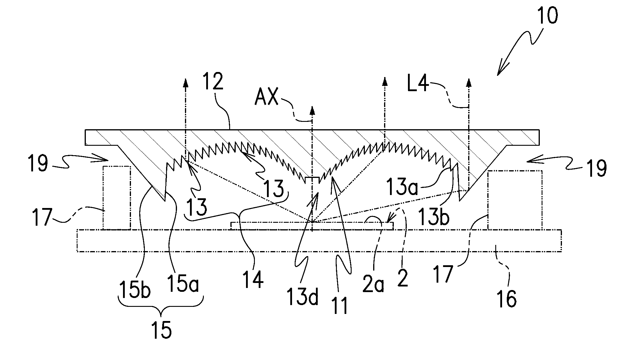
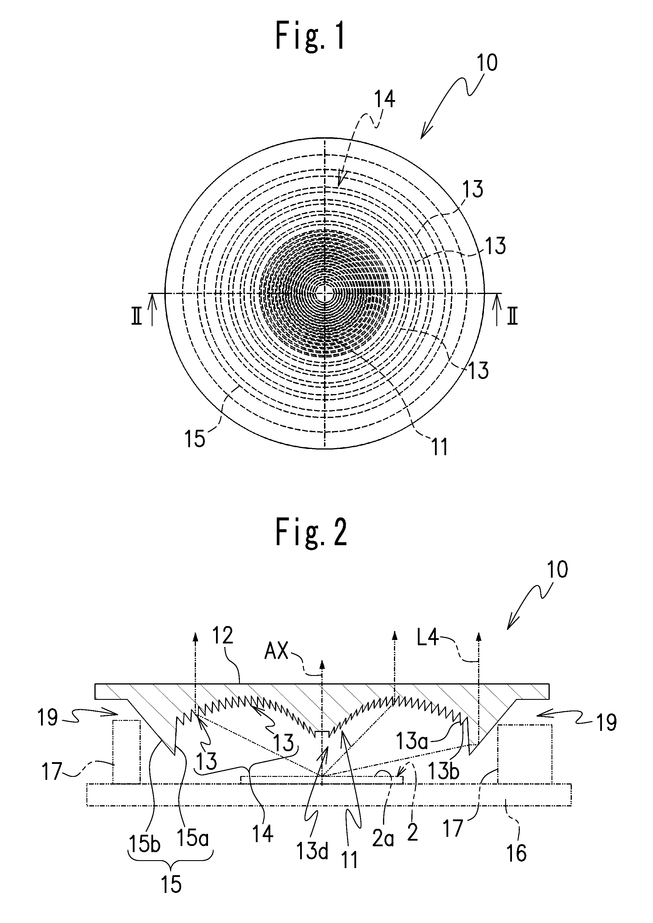
[0037]Consequently, the lens member 10 of the present invention may have a Fresnel-lens surface mentioned above. The lens member 10 has a plate-shape as a whole. The plurality of annular prisms 13 including a plurality of annular inner surfaces 13a and annular outer surfaces 13b of the Fresnel-lens surface 14 may have different light-refracting angles with respect to each other. The Fresnel-lens surface 11 of the lens member 10 is disposed to face a light-emitting surface 2a of a light source 2 with the central axis AX and the center of the light-emitting surface 2a of the light source 2 being coincident with each other. The light source 2 may include at least one LED element. Note that the lens member 10A including the Fresnel-lens surface 11 may be integrally formed by a light-transmitting resin such as acryl resin. Such a provision of the Fresnel-lens surface 14 makes it possible to form a light-exit surface which obtains the strongest light at a central portion and light intens...
second embodiment
[0070]In this way, in the lens member 20 because the annular lens portion 25 is provided annularly about the central axis AX at an intermediate portion of the Fresnel-lens surface 14 between the central axis AX and an outer end portion of the Fresnel-lens surface 14, it is possible to provide a part of the plurality of annular prisms 13 even on an outer side of the annular lens portion 25. In addition, because light entered the annular lens portion 25 is refracted by the annular inner surface 25a and the annular outer surface 25c of the annular lens portion 25, the annular prisms 13 provided outside the annular lens portion 25 can be set at a high position. Consequently, at a position of the annular prisms 13 positioned outside the annular lens portion 25, it is possible to take a large distance between the light-incident side 11 of the lens member 20 and the substrate 16, and secure a large space 29 to house the part 17 for a power circuit at an outer periphery of the annular lens...
third embodiment
[0074]In the lens member 30 because the convex portions 31 having a function to control at least one of diffusivity and directivity of light are formed on the light-exit surface 12, it is easy to emit light that a light path is changed by the annular lens portion 15 to be directed toward the light-exit surface 12 by the convex portions 31 or concave portions provided on the light-exit surface 12 for refraction or diffusion of light with a predetermined diffusivity or directivity. For example, a brightness balance between light that a light path is changed to be directed toward the light-exit surface 12 by the annular lens portion 15 and light that a light path is changed by the annular prisms 13 of the Fresnel-lens surface 14, at the light-exit surface 12 can be adjusted, and a distribution of emitted light can be adjusted.
[0075]Meanwhile, convex or concave portions may be provided on the light-exit surface 12 of the lens member 30 at a position of the light-exit surface facing the...
PUM
 Abstract
Description
Claims
Application Information
 - Generate Ideas
- Intellectual Property
- Life Sciences
- Materials
- Tech Scout
- Unparalleled Data Quality
- Higher Quality Content
- 60% Fewer Hallucinations
Browse by: Latest US Patents, China's latest patents, Technical Efficacy Thesaurus, Application Domain, Technology Topic, Popular Technical Reports.
© 2025 PatSnap. All rights reserved.Legal|Privacy policy|Modern Slavery Act Transparency Statement|Sitemap|About US| Contact US: help@patsnap.com