Method for generating a plurality of optimized wavefronts for a multiple exposure lithographic process

Inactive Publication Date: 2012-03-29
GLOBALFOUNDRIES INC
View PDF1 Cites 9 Cited by
  • Summary
  • Abstract
  • Description
  • Claims
  • Application Information

AI Technical Summary

Benefits of technology

[0021]calculating an optimal wavefront by finding weights for the new set of basis components through minimizing the primary objective function; and g...

Problems solved by technology

This is not the case, however, when the optimization problem has constraints, as the full problem of interest does here.
More specifically, the full problem, which is to minimize dark region intensity...

Method used


Image

  • Method for generating a plurality of optimized wavefronts for a multiple exposure lithographic process
  • Method for generating a plurality of optimized wavefronts for a multiple exposure lithographic process
  • Method for generating a plurality of optimized wavefronts for a multiple exposure lithographic process

Examples


Embodiment Construction

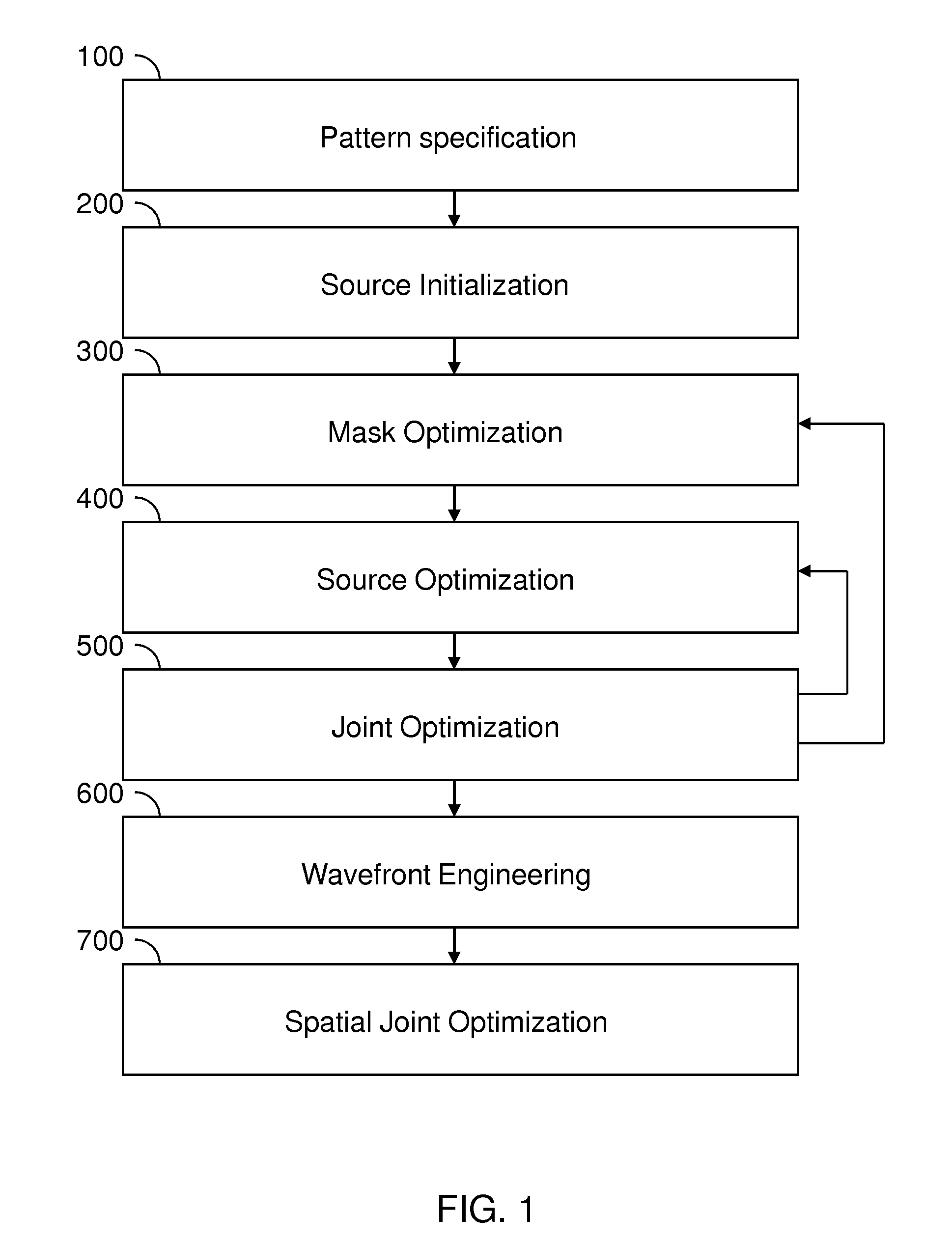
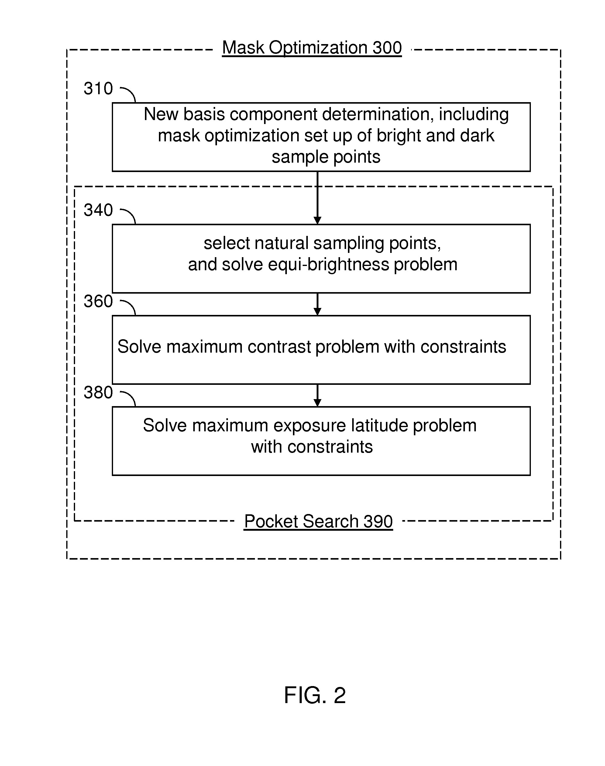
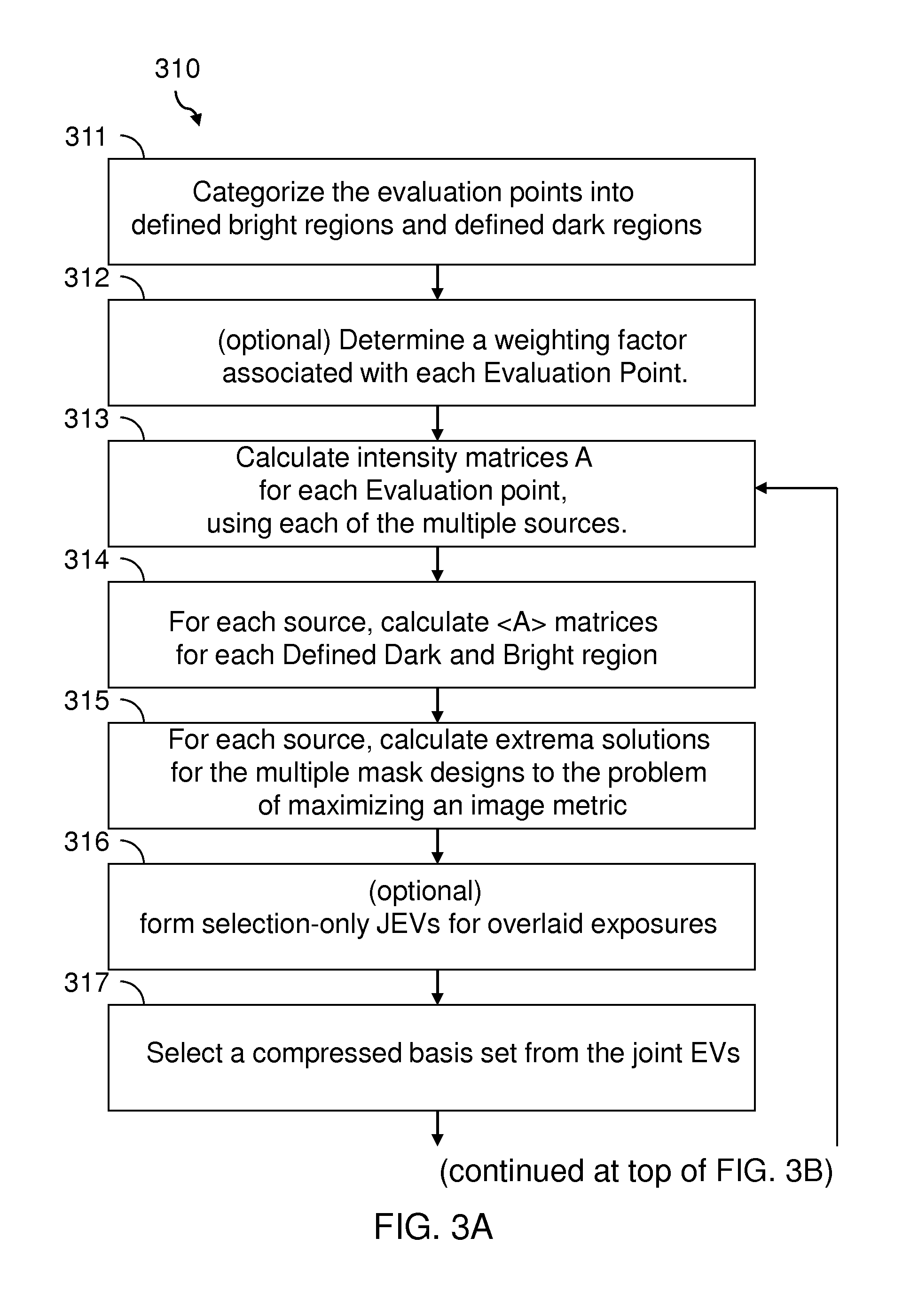
[0026]As stated above, the present disclosure relates to a method for generating a plurality of optimized wavefronts for a multiple exposure lithography process, which is now described in detail with accompanying figures. It is noted that like and corresponding elements are referred to by like reference numerals.

[0027]As used herein, “lithographic fabrication” refers to formation of a lithographic image by at least one exposure step and at least one development step, which may potentially be a self-developing step occurring upon exposure.

[0028]As used herein “multiexposure lithography” refers to a lithographic process that employs multiple masks to provide multiple exposure of a same photoresist to form a single lithographic pattern therein.

[0029]As used herein, a “source” or an “illumination source” refers to a device configured to emit radiation for the purpose of lithographic exposure.

[0030]As used herein, a “source shape” refers to the directional shape of the illumination that ...


PUM


Abstract

A simplified version of a multiexpose mask optimization problem is solved in order to find a compressed space in which to search for the solution to the full problem formulation. The simplification is to reduce the full problem to an unconstrained formulation. The full problem of minimizing dark region intensity while maintaining intensity above threshold at each bright point can be converted to the unconstrained problem of minimizing average dark region intensity per unit of average intensity in the bright regions. The extrema solutions to the simplified problem can be obtained for each source. This set of extrema solutions is then assessed to determine which features are predominantly printed by which source. A minimal set of extrema solutions serves as a space of reduced dimensionality within which to maximize the primary objective under constraints. The space typically has reduced dimensionality through selection of highest quality extrema solutions.

Description

BACKGROUND[0001]The present disclosure relates to lithographic methods, and particularly to a method for generating a plurality of optimized wavefronts for a lithography process.[0002]Printing state-of-the-art circuit patterns with available image-forming technology poses an important challenge for the semiconductor industry. For production costs to be viable the images must be formed with radiation whose wavelength is compatible with practical lenses (for example refractive lenses), and this limits the fundamental resolution of the image. It then becomes desirable to optimize the patterns on the masks which the imaging lenses project on the wafer as a means of forming the circuit pattern image, in order that the available resolution be exploited as fully as possible.[0003]In the case where a single mask is projected to a wafer to form the circuit image (in a particular level), A. E. Rosenbluth, S. Bukofsky, C. Fonseca, M. Hibbs, K. Lai, A. Molless, R. N. Singh, and A. K. K. Wong, “...

Claims


Application Information

Patent Timeline
IPC IPC(8): G03F7/20G06F17/50
CPCG03F7/70466G03F1/68G03F1/70
Inventor BAGHERI, SAEEDLAI, KAFAIMELVILLE, DAVID O.ROSENBLUTH, ALAN E.TIAN, KEHANTIRAPU AZPIROZ, JAIONE
Owner GLOBALFOUNDRIES INC
Why Eureka
Try Eureka