Flip-chip bonding method to reduce voids in underfill material

a bonding method and underfill material technology, applied in semiconductor devices, semiconductor/solid-state device details, electrical apparatus, etc., can solve the problems of reliability problems, reliability issues, reliability issues of 3d ic packages, etc., to reduce the bubbles trapped inside the underfill material, reduce the voids in the underfill material, and avoid poor adhesion

Inactive Publication Date: 2012-03-29
WALTON ADVANCED ENG INC
View PDF3 Cites 27 Cited by
  • Summary
  • Abstract
  • Description
  • Claims
  • Application Information

AI Technical Summary

Benefits of technology

[0005]The main purpose of the present invention is to provide a flip-chip bonding method to reduce voids in underfill material

Problems solved by technology

Especially, when multiple chips are stacked, the gaps between the chips are even smaller and far away from the substrate where underfill material can not easily fill into the gaps so that voids or bubbles are easily formed and trapped inside the underfill material.
Due to CTE mismatch between a chip and a substrate during thermal cycling processes, popcorn defects are easily occurred leading to reliability issues.
When vertically stacking a plurality of chips in a 3D structure,

Method used


Image

  • Flip-chip bonding method to reduce voids in underfill material
  • Flip-chip bonding method to reduce voids in underfill material
  • Flip-chip bonding method to reduce voids in underfill material

Examples


Embodiment Construction

[0014]With reference to the attached drawings, the present invention is described by means of the embodiment(s) below where the attached drawings are simplified for illustration purposes only to illustrate the structures or methods of the present invention by describing the relationships between the components and assembly in the present invention. Therefore, the components shown in the figures are not expressed with the actual numbers, actual shapes, actual dimensions, nor with the actual ratio. Some of the dimensions or dimension ratios have been enlarged or simplified to provide a better illustration. The actual numbers, actual shapes, or actual dimension ratios can be selectively designed and disposed and the detail component layouts may be more complicated.

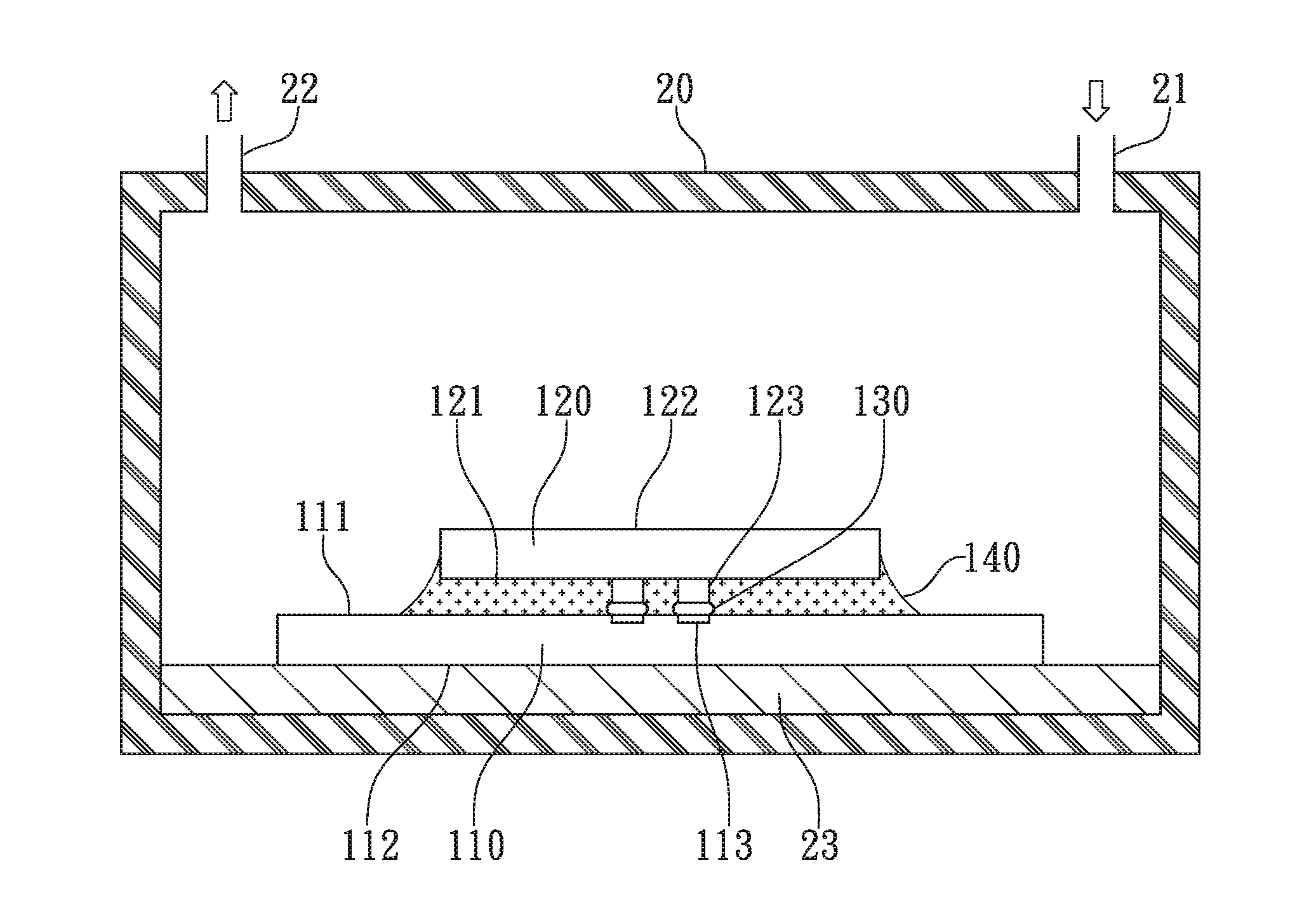
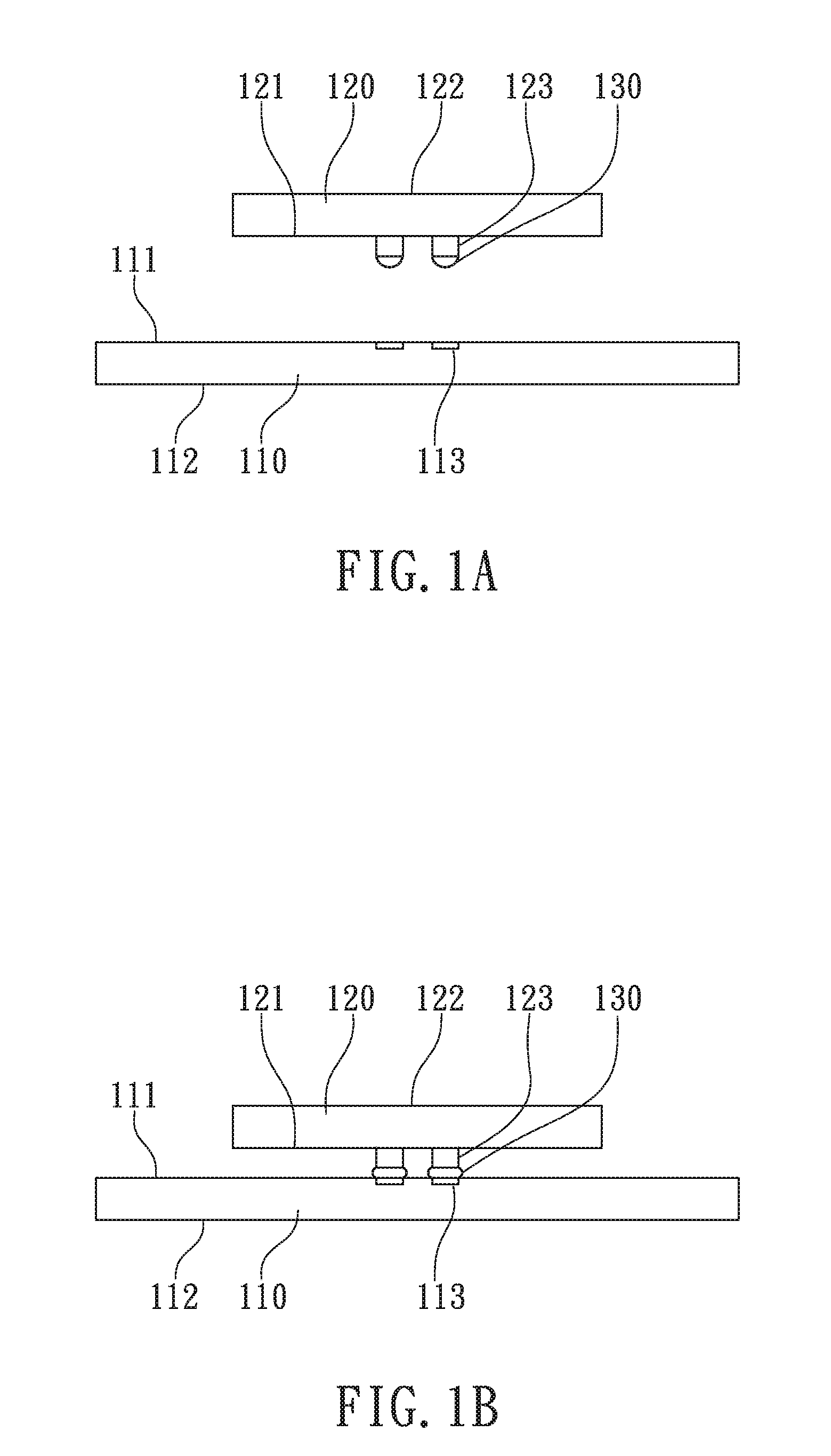
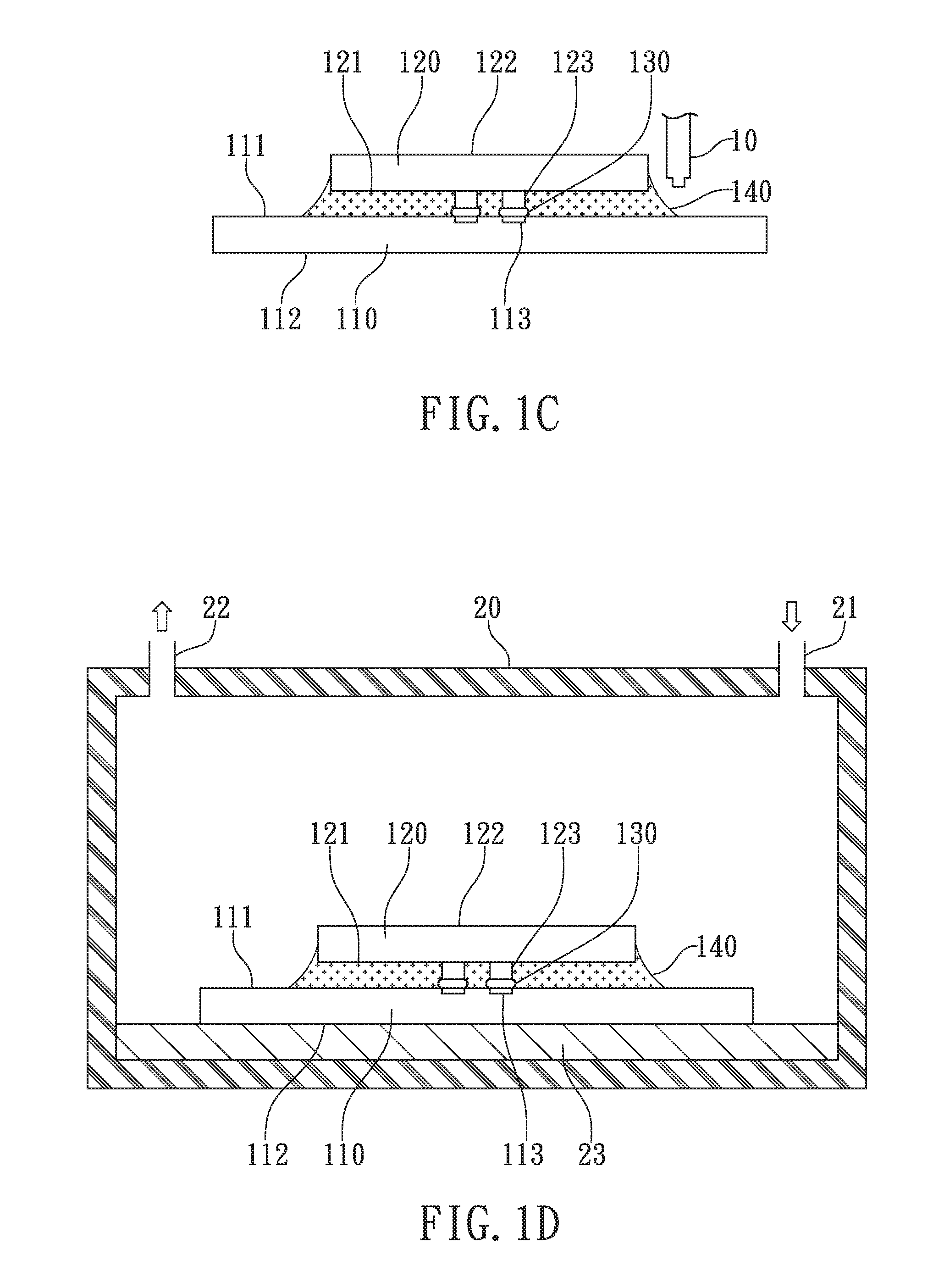
[0015]According to the first embodiment of the present invention, a flip-chip bonding method to reduce voids in underfill material is illustrated from FIG. 1A to FIG. 1E for cross-sectional views of each processing step.

[0016...


PUM


Abstract

Disclosed is a flip-chip bonding method to reduce voids in underfill material. A substrate with connecting pads is provided. At least a chip with a plurality of bumps is bonded on the substrate and then an underfill material is formed between the chip and the substrate. Finally, the substrate is placed in a pressure oven in which a positive pressure greater than one atm is provided, meanwhile, the underfill material is thermally cured with exerted pressures to reduce bubbles or voids trapped inside the underfill material to avoid popcorn issues due to CTE mismatch between the chip and the substrate. In one embodiment, another underfill material is further formed between a plurality of chips and bubbles or voids trapped between the chips are also reduced by the pressurized curing.

Description

FIELD OF THE INVENTION[0001]The present invention relates to packaging technology of semiconductor devices, and more specifically to a flip-chip bonding method to reduce voids in underfill material.BACKGROUND OF THE INVENTION[0002]Flip-chip packaging technology is an advanced packaging technology to electrically connect a chip to a substrate with the advantages of smaller footprint and shorter electrical paths. In order to fully attach a chip to a substrate, an underfill material with fluidity is widely used to fill into the gap between the chip and the substrate to compensate CTE mismatch, to completely adhere the chip to the substrate, and to protect the electrical connections between the chip and the substrate from the influence of environment such as stresses, moisture, particles, and others.[0003]However, under the developing trend of high density and miniature, the gap between a chip and a substrate becomes smaller and smaller with more and more connecting terminals such as bu...

Claims


Application Information

Patent Timeline
IPC IPC(8): H01L21/56
CPCH01L21/563H01L2224/0401H01L24/05H01L24/06H01L24/13H01L24/16H01L24/73H01L24/83H01L24/92H01L24/94H01L25/0657H01L25/50H01L2224/05624H01L2224/05647H01L2224/06155H01L2224/06156H01L2224/1308H01L2224/13082H01L2224/131H01L2224/13111H01L2224/13124H01L2224/13144H01L2224/13147H01L2224/1319H01L2224/1329H01L2224/133H01L2224/13562H01L2224/16145H01L2224/16146H01L2224/16225H01L2224/16227H01L2224/16245H01L2224/73104H01L2224/73204H01L2224/83102H01L2224/83192H01L2224/92125H01L2224/94H01L2225/06513H01L2225/06517H01L2225/06541H01L2225/06565H01L2225/06568H01L23/3121H01L2924/01029H01L2224/32225H01L2224/32145H01L24/75H01L2924/01079H01L2924/00013H01L2924/014H01L2924/00014H01L2924/01047H01L2924/01082H01L2224/13099H01L2924/00H01L2924/3512H01L2924/15787H01L2924/181H01L2924/351H01L2924/00012
Inventor LEE, KUO-YUANCHEN, YUNG-HSIANGCHIU, WEN-CHUNLIN, KAO-HSIUNG
Owner WALTON ADVANCED ENG INC
Why Eureka
Try Eureka