Thermal Power Plant

a technology of thermal expansion and boiler, which is applied in the direction of fluidised bed boiler, steam boiler components, combustion process, etc., can solve the problems of high thermal expansion of the hanger rod, long hanger rods are problematic, and endure much compression or bending, so as to minimize the stress caused by thermal expansion

Active Publication Date: 2012-04-05
AMEC FOSTER WHEELER ENERGIA
View PDF15 Cites 6 Cited by
  • Summary
  • Abstract
  • Description
  • Claims
  • Application Information

AI Technical Summary

Benefits of technology

[0025]Since the width of the side walls of the furnace in a large thermal power boiler can be tens of meters, for example, about forty meters, the thermal expansion of the furnace walls downwards and sideways during the start-up of a boiler is significant. As the changes in the temperature of the intermediary supporting beams are significantly less than the changes in the temperature of the furnace, the thermal expansion causes considerable stress in the lower

Problems solved by technology

The furnace walls in the modern thermal power boilers are usually relatively light water tube walls, which have a high tensile strength, but they do not endure much compression or bending.
Long hanger rods are problematic, especially because the temperature of the hanger rods mounted to the upper portion of the

Method used


Image

  • Thermal Power Plant
  • Thermal Power Plant

Examples


Embodiment Construction

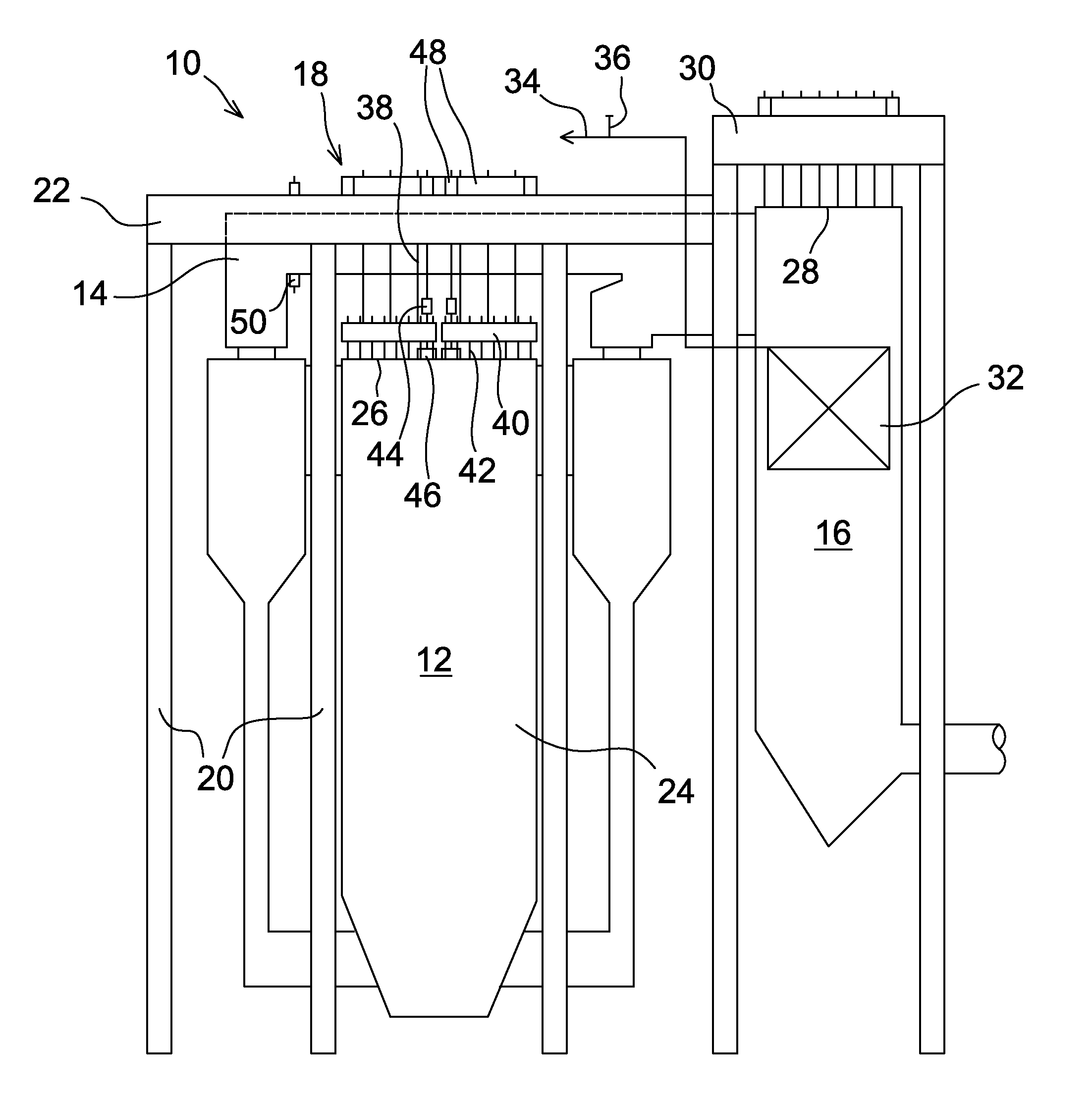
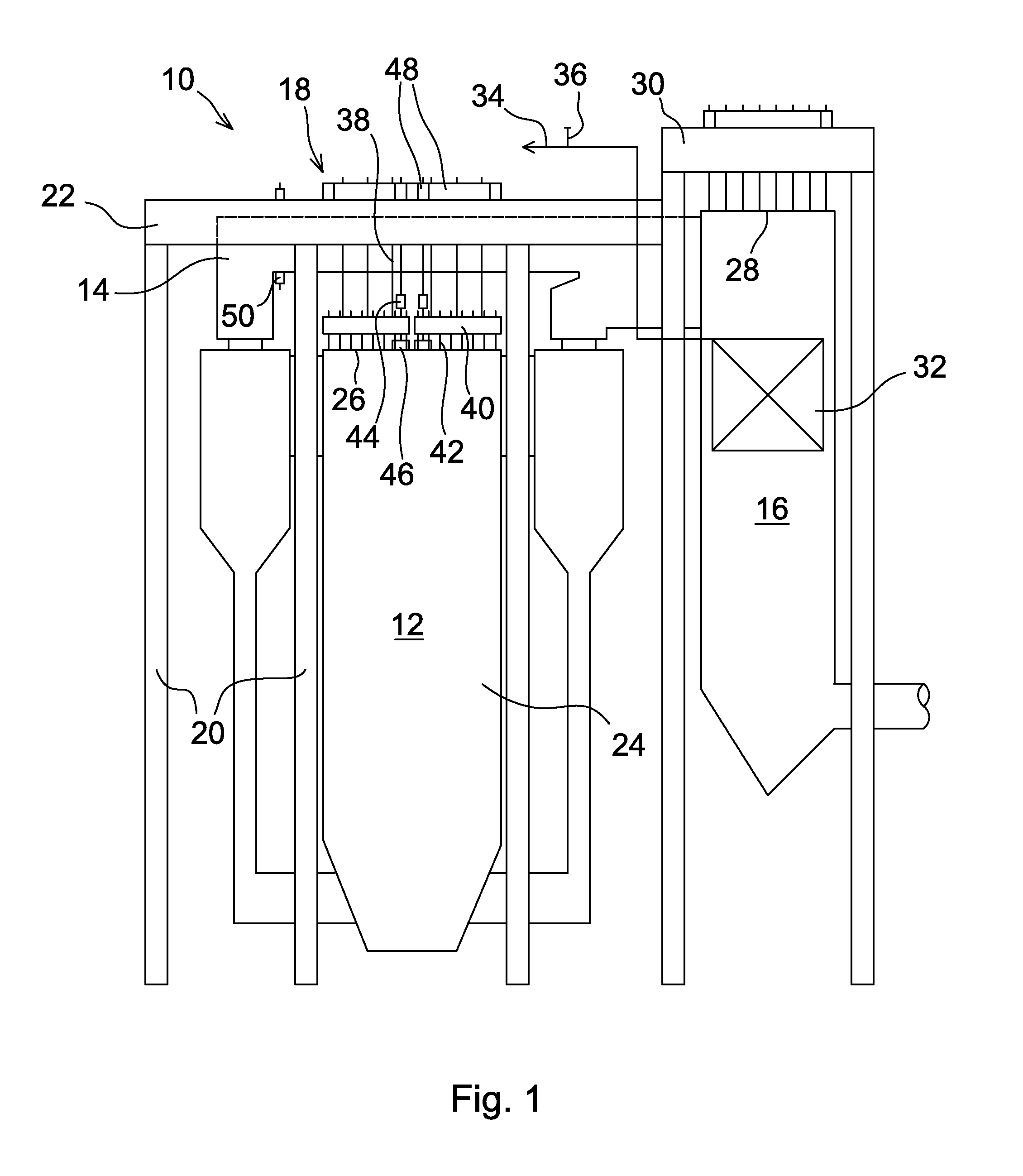
[0028]A circulating fluidized bed boiler plant 10 shown in FIG. 1 is an example of a thermal power boiler plant in accordance with the present invention. The circulating fluidized bed boiler plant 10 comprises a boiler structure having a furnace, flue gas channels 14 arranged above the furnace, a back pass 16, as well as a supporting structure having, as main parts, a suspension structure 18 and a bearing structure, the bearing structure comprising pillars 20 and main supporting beams 22 of the furnace parallel with the flue gas channels and supported by the vertical pillars.

[0029]The furnace is enclosed by two short side walls and two long side walls of which only one side wall 24 is shown in FIG. 1. As can be seen in FIG. 1, both the flue gas channels 14 and the main supporting beams 22 are traverse relative to the furnace, in other words, parallel to the short side walls 24 of the furnace. FIG. 1 only shows one main supporting beams 22 of the furnace and one flue gas channel 14 p...


PUM


Abstract

A thermal power boiler includes a furnace enclosed by two short side walls and two long side walls, flue gas channels arranged above the furnace, a back pass and a supporting structure. The supporting structure includes a stationary bearing structure supported from below. The bearing structure includes multiple vertical pillars and a parallel main supporting beams supported by the vertical pillars, and a suspension structure, so that the furnace hangs from the bearing structure. The main supporting beams and the flue gas channels arranged above the furnace are parallel with each other and parallel with the short side walls. The main supporting beams are preferably arranged at least partially between the flue gas channels extending over the roof of the furnace.

Description

[0001]This application is a U.S. national stage application of PCT International Application No. PCT / FI2010 / 050282, filed Apr. 8, 2010, published as PCT Publication No. WO 2010 / 116040 A2, and which claims priority from Finnish patent application number 20095401, filed Apr. 9, 2009.FIELD OF THE INVENTION[0002]The present invention relates to a thermal power boiler plant. The invention more particularly relates to a thermal power boiler plant comprising a furnace enclosed by two short side walls and two long side walls, a flue gas channel arranged above the furnace, a back pass and a supporting structure, which supporting structure comprises a stationary bearing structure supported from below, the bearing structure comprising multiple vertical pillars and main supporting beams supported by the vertical pillars, and a suspension structure, by means of which the furnace hangs from the bearing structure.[0003]There is a tendency to increase the capacity of thermal power boilers, such as ...

Claims


Application Information

Patent Timeline
IPC IPC(8): F22B37/24
CPCF22B31/0007F22B37/244F23M5/00F23C10/18F23C10/10F22B37/64
Inventor LANKINEN, PENTTI
Owner AMEC FOSTER WHEELER ENERGIA
Why Eureka
Try Eureka