Preloaded piezo actuator and gas valve employing the actuator

a piezo actuator and actuator technology, applied in the direction of diaphragm valves, valve housings, engine diaphragms, etc., can solve the problems of not providing provisions for protecting the piezoelectric element from the environment, and not providing provisions for properly preloading the piezoelectric element for operation in elevated temperatures and high moisture environments, etc., to achieve constant preloading and minimize thermal expansion

Active Publication Date: 2021-01-14
PIVOTAL SYST CORP
View PDF0 Cites 0 Cited by
  • Summary
  • Abstract
  • Description
  • Claims
  • Application Information

AI Technical Summary

Benefits of technology

[0008]An arrangement is provided for a piezoelectric actuator, wherein the arrangement provides preloading and protection of the piezoelectric element. The piezoelectric element is enclosed in a housing that protects the piezoelectric element, while also enabling transfer of the motion actuation outside the housing. In certain embodiments the housing is made of a material that minimizes thermal expansion in order to maintain constant preloading. In such embodiments the casing may be made of a nickel-iron alloy, also referred to as Invar, such as Invar 36®, available from Carpenter Technology Corporation of Philadelphia, Pa. In other embodiments the housing is made of a nickel cobalt alloy, such as Kovar, also available from Carpenter Technology Corporation. In yet other embodiments, the housing is made of Inovko, available from Nordt EPM of Roanoke, Va.

Problems solved by technology

Arrangements for preloading the piezoelectric element are disclosed in, e.g., U.S. Pat. No. 7,859,169; however, in this and other publications no provisions are provided for protecting the piezoelectric element from the environment.
While these valves may function properly in some environments, no provisions are disclosed for properly preloading the piezoelectric element, nor for protecting the piezoelectric element for operation in elevated temperatures and high moisture environments.

Method used


Image

  • Preloaded piezo actuator and gas valve employing the actuator
  • Preloaded piezo actuator and gas valve employing the actuator
  • Preloaded piezo actuator and gas valve employing the actuator

Examples


Embodiment Construction

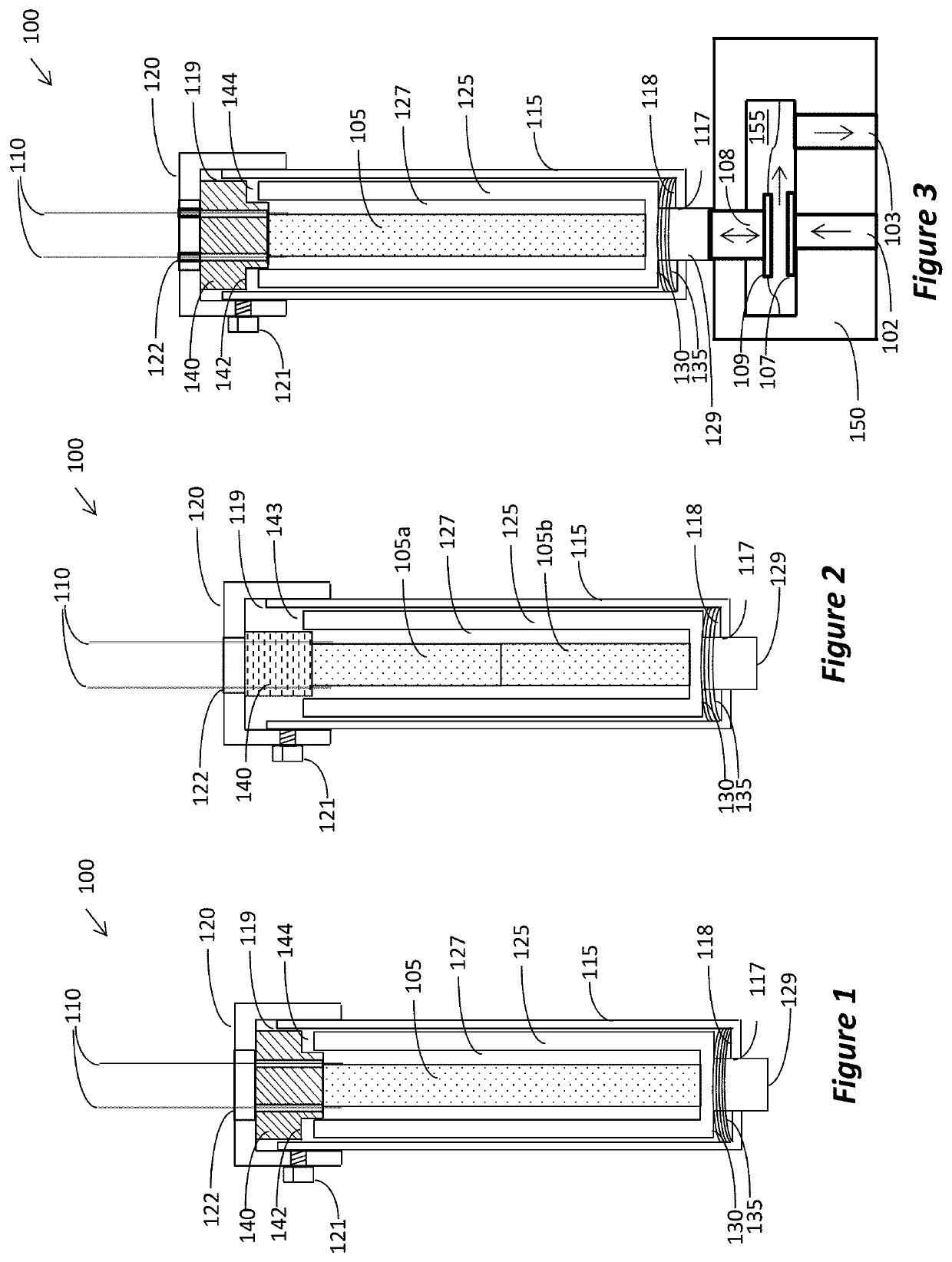
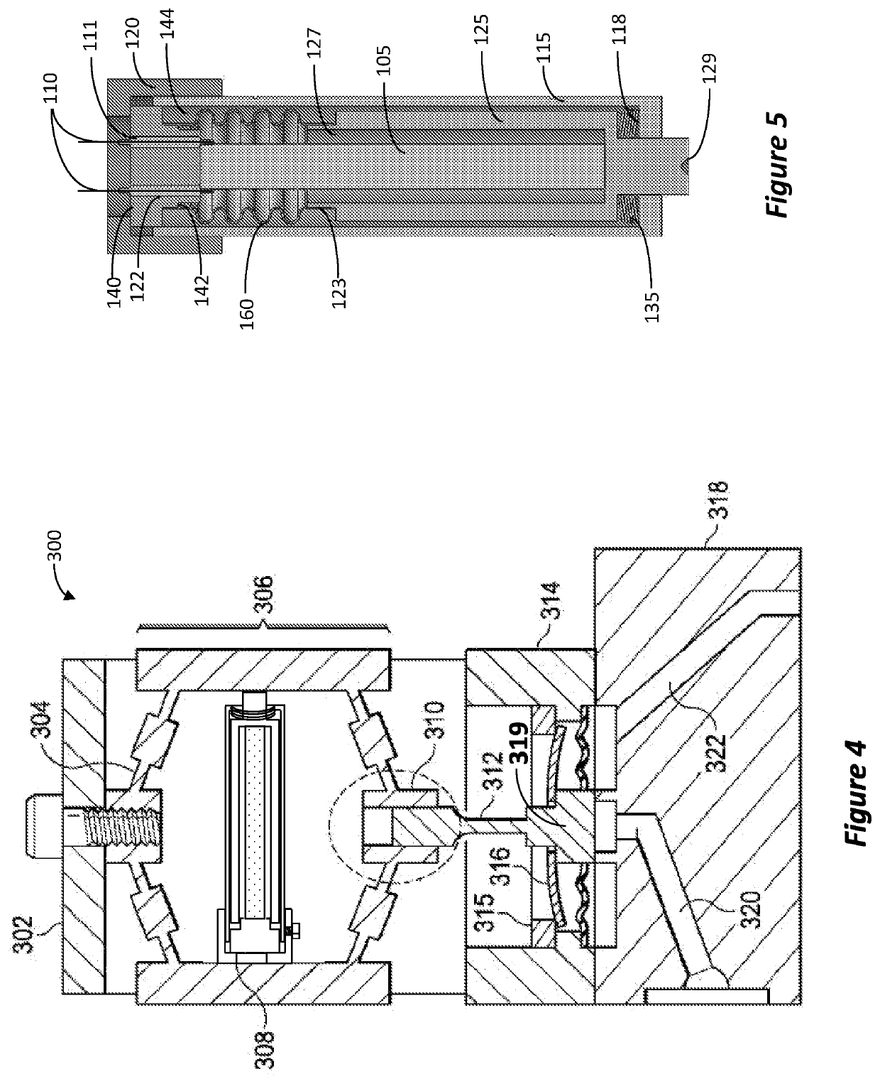
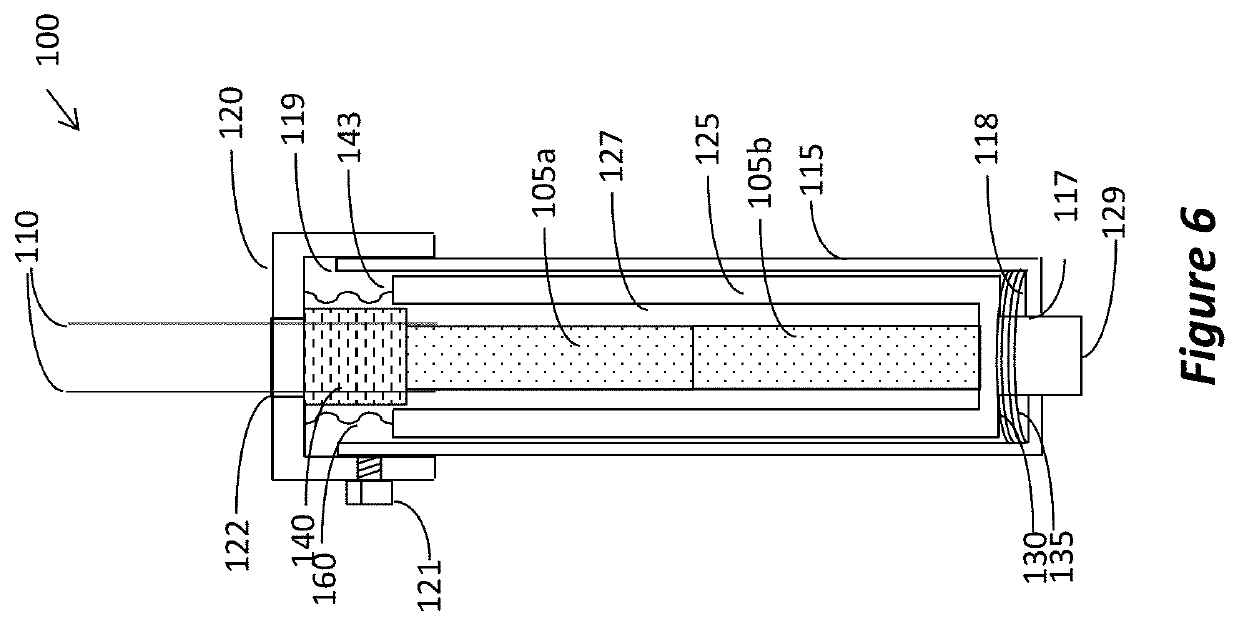
[0020]Embodiments of the inventive actuator will now be described with reference to the drawings. Different embodiments or their combinations may be used for different applications or to achieve different benefits. Depending on the outcome sought to be achieved, different features disclosed herein may be utilized partially or to their fullest, alone or in combination with other features, balancing advantages with requirements and constraints. Therefore, certain benefits will be highlighted with reference to different embodiments, but are not limited to the disclosed embodiments. That is, the features disclosed herein are not limited to the embodiment within which they are described, but may be “mixed and matched” with other features and incorporated in other embodiments.

[0021]The following embodiments disclose an arrangement for an actuator which utilizes a piezoelectric element that is preloaded and protected from the environment. As non-limiting examples of piezoelectric elements ...


PUM


Abstract

A valve arrangement for controlling gas flow. A gas block includes a gas inlet, a gas outlet, and a gas cavity fluidly connecting the gas inlet to the gas outlet. A diaphragm is configured for controlling gas flow between the gas inlet and the gas outlet. An actuator is configured to vary the position of the diaphragm so as to control the gas flow. The actuator comprises a tubular housing; a plunger positioned inside the housing and having an actuating extension extending outside of the housing and coupled to the diaphragm, the plunger configured to be slidable inside the housing; a piezoelectric body positioned inside the plunger; and a pre-loader applying force to the plunger so as to press the plunger against the piezoelectric body.

Description

BACKGROUND1. Field[0001]This disclosure relates to piezoelectric actuators and a structure that transfers the expansion of the piezoelectric element, while protecting the element from the environment. The disclosure also relates to valves for controlling gas flow, especially valves employing piezoelectric actuators.2. Related Art and Problem Being Solved[0002]Actuators employing the expansion of piezoelectric elements upon application of voltage potential are known in the art. Arrangements for preloading the piezoelectric element are disclosed in, e.g., U.S. Pat. No. 7,859,169; however, in this and other publications no provisions are provided for protecting the piezoelectric element from the environment.[0003]Accordingly, there is a need for a piezoelectric element arrangement that provide preloading and protection for the piezoelectric element. Also, arrangements are needed which can operate in high temperatures, e.g., up to 200° C. and provide protection from ambient moisture.[00...

Claims


Application Information

Patent Timeline
Patent Type & Authority Applications(United States)
IPC IPC(8): F16K31/00F16K7/00F16K27/02
CPCF16K31/004F16K27/0236F16K7/00F16K31/007F16K41/10F16K27/02F16K7/12
Inventor BROWN, TIMOTHY R.
Owner PIVOTAL SYST CORP
Why Eureka
Try Eureka