Top entry plastic ball valve

Active Publication Date: 2012-04-05
GUANGDONG LIANSU TECH INDAL
View PDF7 Cites 1 Cited by
  • Summary
  • Abstract
  • Description
  • Claims
  • Application Information

AI Technical Summary

Benefits of technology

[0023]In the invention, a top entry structure of the valve cover is provided just above the valve body, wherein two valve ball sealing rings are directly mounted on the valve body such that the axial distance between the two sealing rings can be accurately controlled, and accordingly, the pre-stressed force of the sealing surface and the torsional moment of the valve stem can be effectively controlled, thereby solving the problem in the prior art of low qualificatio

Problems solved by technology

The hot melt welding has simple process, low cost and relative low accuracy; and the electric fusion welding has complex process and high cost.
However, in such structure, the designed pressing force is obtained through the two buckling parts on three parts, which brings more difficulties for manufacture and assembly;
Large insertion depth causes large pre-stressed force and large torques for opening and closing the valve and serious abrasion; small insertion depth brings small pre-stressed force of the sealing surface, thereby causing a hidden danger of inner leakage.
In addition, it is difficult to ensure coincidence of central lines o

Method used


Image

  • Top entry plastic ball valve
  • Top entry plastic ball valve
  • Top entry plastic ball valve

Examples


Embodiment Construction

[0031]The invention is further described by combining the drawings:

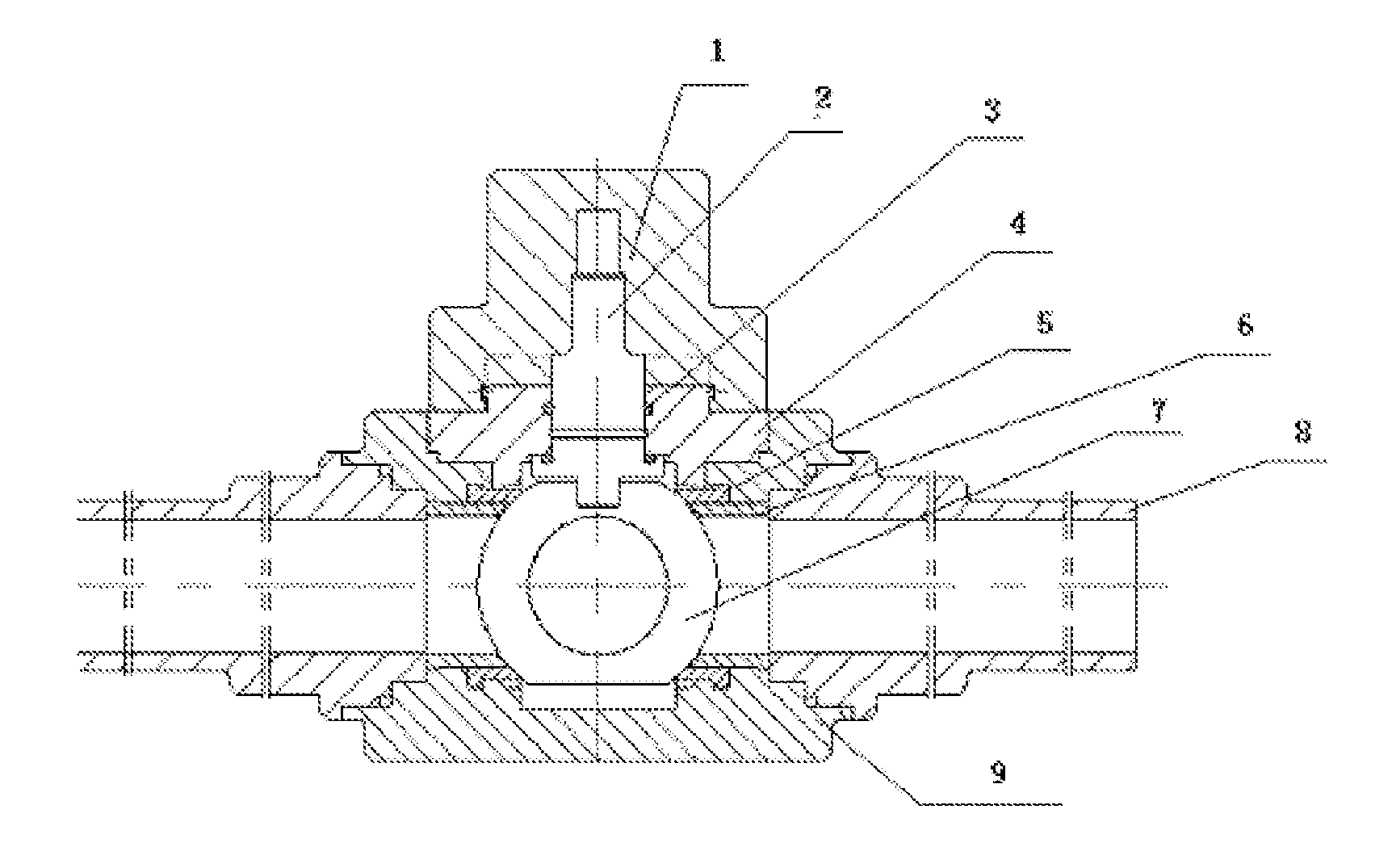
[0032]Referring to the diagram of the whole structure of the PE ball valve as shown in FIG. 1, the plastic ball valve of the invention comprise a valve stem cap 1, a valve stem 2, a valve stem sealing ring 3, a valve cover 4, a valve ball sealing ring 5, a supporting ring 6 for the valve ball sealing ring, a valve ball 7, a connecting pipe 8 and a valve body 9.

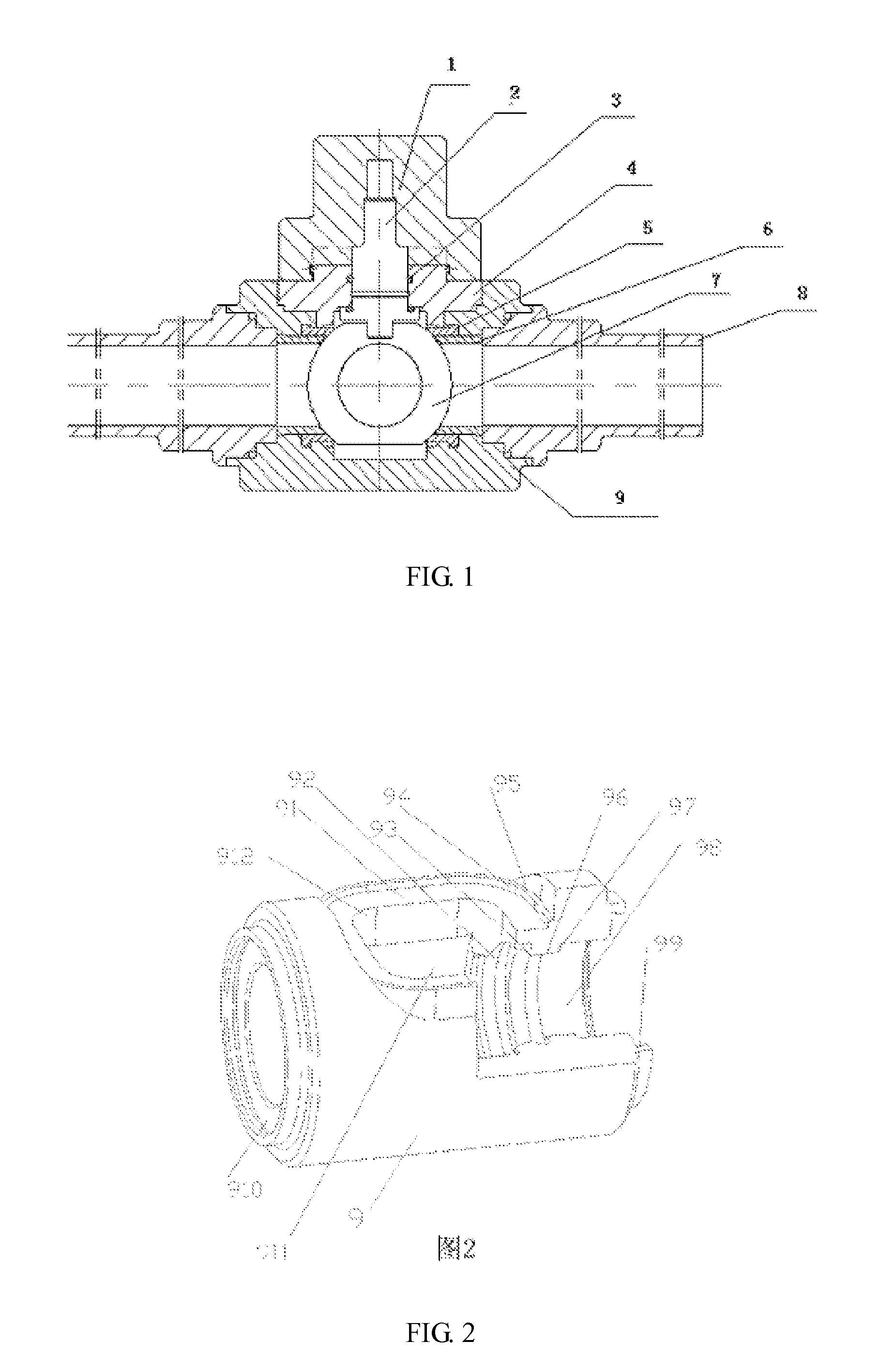
[0033]Referring to the structural diagrams of the valve body of the PE ball valve as shown in FIG. 2, said valve body 9 substantially is a cylinder which is internally provided with a series of cylindrical holes communicated with each other, and the axial lines of the cylindrical holes coincide with the cylinder body of the valve body in axial direction. The valve body 9 comprises a melt adhesive surface 91 of the valve cover, a circumferential positioning surface 94 of the valve cover, an axial positioning surface 95 of the valve cover, an inner cylindrical su...


PUM

PropertyMeasurementUnit
Shapeaaaaaaaaaa

Abstract

A top entry plastic ball valve comprises a valve stem cap (1), a valve stem (2), a valve stem sealing ring (3), a valve ball sealing ring (5), a supporting ring (6) for the valve ball sealing ring, a valve ball (7), a connecting pipe (8), and a valve body (9). A hollow valve ball chamber (911) is provided inside the valve body (9), the valve body (9) is provided with a valve cover hole (912) just above the valve ball chamber (911), and the width of the valve cover hole (912) is larger than the diameter of the valve ball (7). The ball valve also comprises a valve cover (4), which is provided with a valve stem shaft hole (410) for allowing the valve stem (2) to pass through and corresponds to the valve cover hole (912) so that the valve cover (4) can cover the valve cover hole (912) and can be fusion-bonded to the valve body (9), thereby avoiding the need for electric fusion welding process in the manufacture of large-diameter ball valves.

Description

FIELD OF THE INVENTION[0001]The invention belongs to the field of plastic ball valves, and particularly relates to a top entry plastic ball valve.BACKGROUND OF THE INVENTION[0002]With wide application of plastic gas pipelines, plastic ball valve is firstly developed and manufactured in USA and widely applied to plastic gas pipeline systems to meet the needs of forming pipeline systems. People have been gradually realized the superiority of plastic ball valves in respects of performances / price and began to replace metal ball valves with plastic ball valves.[0003]For traditional plastic valves, a small-diameter ball valve is integrated by hot melt welding, and a large-diameter ball valve adopts electric fusion welding. The hot melt welding has simple process, low cost and relative low accuracy; and the electric fusion welding has complex process and high cost.[0004]Presently, the valve structure with hot melt welding commonly adopts an integral side-entry structure, in which a ball bo...

Claims


Application Information

Patent Timeline
IPC IPC(8): F16K5/06
CPCF16L47/02F16K5/0636Y10T137/6038
Inventor YANG, JIYUEHUANG, HONGBIN
Owner GUANGDONG LIANSU TECH INDAL
Why Eureka
Try Eureka