Temperature controlling system for LED module

a technology of led modules and temperature control systems, which is applied in the direction of gas-filled discharge tubes, semiconductor devices of light sources, lighting and heating apparatus, etc., can solve the problems of limited heat-dissipating effect achieved by heat-dissipating fins, unstable led units, and limited heat-dissipation effect, etc., to achieve uniform heat-dissipation

Active Publication Date: 2012-04-05
ASIA VITAL COMPONENTS SHENZHEN CO LTD
View PDF6 Cites 10 Cited by
  • Summary
  • Abstract
  • Description
  • Claims
  • Application Information

AI Technical Summary

Benefits of technology

[0010]In order to solve the above problems, an objective of the present invention is to provide a temperature controlling system for a LED module, which has a uniform heat-dissipating effect.
[0013]According to the present invention, the LED unit, the fan, the temperature sensor and the control device are integrated into the LED module, so that the working temperature of the respective LED units can be kept the same and a uniform heat-dissipating effect can be achieved.

Problems solved by technology

When a LED lamp is in operation, a plurality of LED units mounted therein generates a great amount of heat due to their poor energy conversion efficiency of electricity to optical energy, so that the heat is accumulated in the LED lamp to make the LED units unstable.
Therefore, it is an important issue to rapidly dissipate the heat generated by the LED unit to the outside.
However, the heat-dissipating effect achieved by the heat-dissipating fins only is so limited that a fan is additionally mounted to the heat-dissipating fins for achieving a compulsive heat-dissipating effect.
Although the heat generated by the LED lamp can be dissipated to the outside by the combination of the heat-dissipating fins and the fan, the heat-dissipating effect achieved by such a combination is still insufficient.
As a result, it is unable to dissipate the heat of the respective LED units uniformly due to the temperature and humidity of the ambient environment, so that the degree of heat conduction and heat convection varies throughout the interior of the LED lamp.
Thus, the working temperatures of the respective LED units are different from each other, which may reduce the lifetime of some LED units.
According to the above, the conventional LED lamp has the following problems: (1) the heat-dissipating effect is not uniform; (2) the lifetime is shortened; and (3) the working temperature and the attenuation degree of brightness of the respective LED units are different from each other.

Method used


Image

  • Temperature controlling system for LED module
  • Temperature controlling system for LED module
  • Temperature controlling system for LED module

Examples


Embodiment Construction

[0016]The above objectives and structural and functional features of the present invention will be described in more detail with reference to preferred embodiment thereof shown in the accompanying drawings

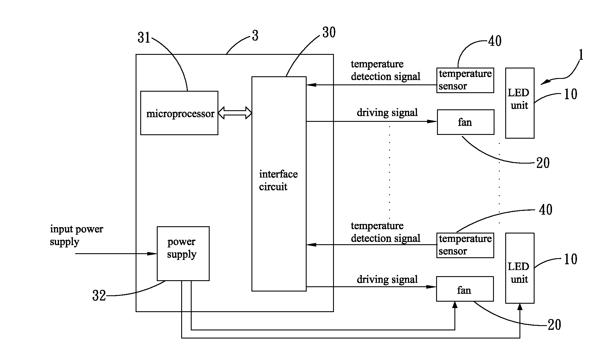
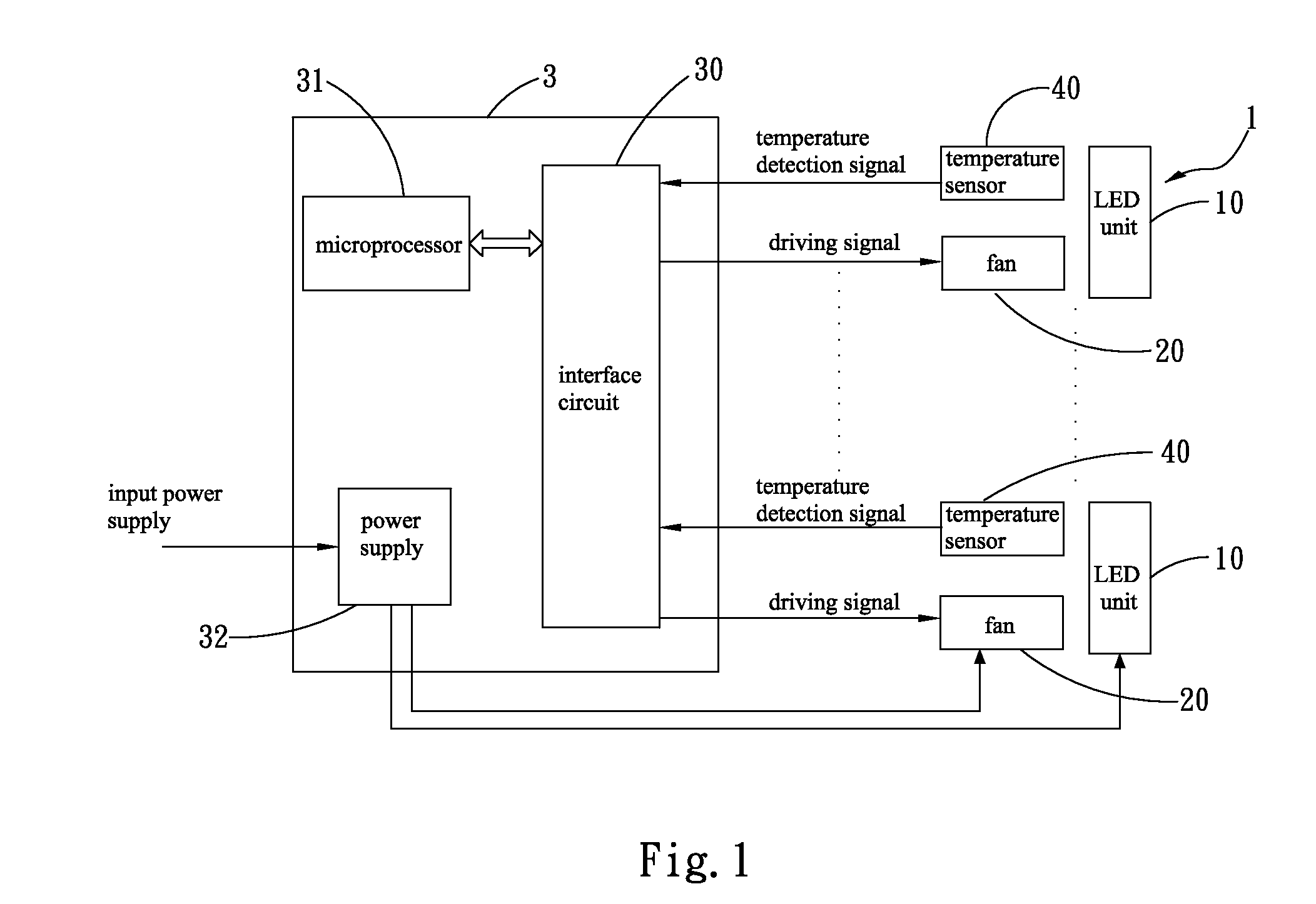
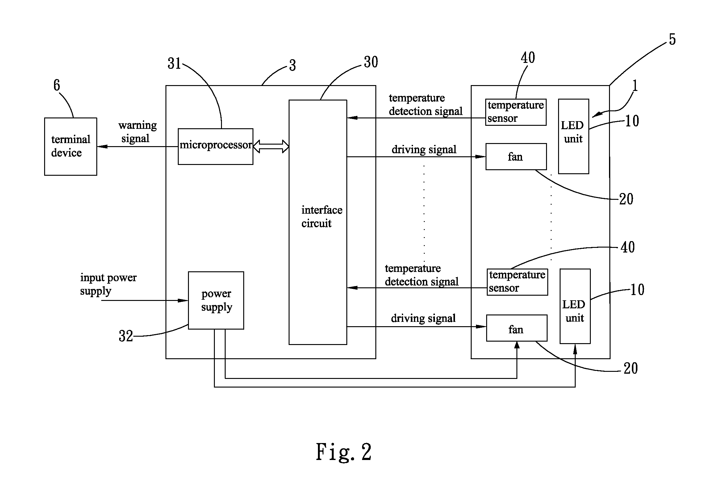
[0017]Please refer to FIGS. 1 and 2. The present invention is directed to a temperature controlling system for a LED module, which includes at least one LED unit 10, at least one fan 20, at least one temperature sensor 40 and a control device 3. The LED unit 10 has a plurality of LED chips. The LED units 10 constitute a LED module 1. The LED module 1 is mounted in a light-emitting device 5 such as a LED signboard, a LED lamp or the like. In the present embodiment, the light-emitting device 5 is exemplified as a LED lamp, but it is not limited thereto.

[0018]The fan 20 is provided on one side corresponding to the LED unit 10 for compulsively dissipating the heat generated by the LED unit 10. The temperature sensor 40 is positioned adjacent to the fan 20 for detecting an ambient tempe...


PUM


Abstract

A temperature controlling system for a LED module includes at least one LED unit, at least one fan, at least one temperature sensor and a controlling device. The controlling device generates a driving signal for controlling the rotating speed of the fan based on a temperature detection signal transmitted from the temperature sensor, so that the fan can generate a compulsive airflow for dissipating the heat generated by the LED unit. According to the present invention, the working temperatures of the respective LED units can be kept the same, and a uniform heat-dissipating effect can be achieved.

Description

BACKGROUND OF THE INVENTION[0001]1. Field of the Invention[0002]The present invention relates to a temperature controlling system for a LED module, and in particular to a temperature controlling system for a LED module, whereby the working temperatures of the respective LED units can be kept the same and a uniform heat-dissipating effect can be achieved.[0003]2. Description of Prior Art[0004]With the advancement of science and technology, light-emitting diodes (referred to as “LED” hereinafter) are advantageous over traditional bulbs in terms of brightness, power, lifetime, electricity consumption and response time, so that the LEDs have been widely used in lamps, signboards and indoor illumination to replace the traditional bulbs.[0005]When a LED lamp is in operation, a plurality of LED units mounted therein generates a great amount of heat due to their poor energy conversion efficiency of electricity to optical energy, so that the heat is accumulated in the LED lamp to make the LE...

Claims


Application Information

Patent Timeline
Patent Type & Authority Applications(United States)
IPC IPC(8): F21V29/00
CPCF21Y2101/02F21V29/677H05B33/0854F21Y2115/10H05B45/18
Inventor SUN, SUNG-HSIENCHANG, BOR-HAW
Owner ASIA VITAL COMPONENTS SHENZHEN CO LTD
Why Eureka
Try Eureka