Inverted-U Crossed-Dipole Satcom Antenna

a satcom antenna and cross-dipole technology, applied in the field of satellite communication (satcom) antennas, can solve the problems of difficult to guarantee, unsuitable antennas, difficult to choose, etc., and achieve the effect of improving radiation patterns and physical assembly advantages

Inactive Publication Date: 2012-04-05
REGALA FLORENIO PINILI
View PDF6 Cites 18 Cited by
  • Summary
  • Abstract
  • Description
  • Claims
  • Application Information

AI Technical Summary

Benefits of technology

[0020]The invention provides an inverted-u crossed-dipole SATCOM antenna that overcomes the hereinafore-mentioned disadvantages of the heretofo...

Problems solved by technology

However, for communication in directions nearing the axial direction of the monopole/dipole, these antennas are not good choices.
Because satellites orbit the earth and transmit to receivers in multiple directions and orientations, it is simply not possible, or at least, excessively difficult to guarantee that the antenna that is communicating with the orbiting satellite has a physical orientation that matches that of the satellite.
For this reason, single-plane transmission with satellites is not practical.
This directionality is disadvantageous because, with satellite communication, the nearest satellite is always the one most directly above the antenna and the furthest satellites are the ones at low angles to the antenna.
Becau...

Method used


Image

  • Inverted-U Crossed-Dipole Satcom Antenna
  • Inverted-U Crossed-Dipole Satcom Antenna
  • Inverted-U Crossed-Dipole Satcom Antenna

Examples


Embodiment Construction

[0052]While the specification concludes with claims defining the features of the invention that are regarded as novel, it is believed that the invention will be better understood from a consideration of the following description in conjunction with the drawing figures, in which like reference numerals are carried forward. It is to be understood that the disclosed embodiments are merely exemplary of the invention, which can be embodied in various forms.

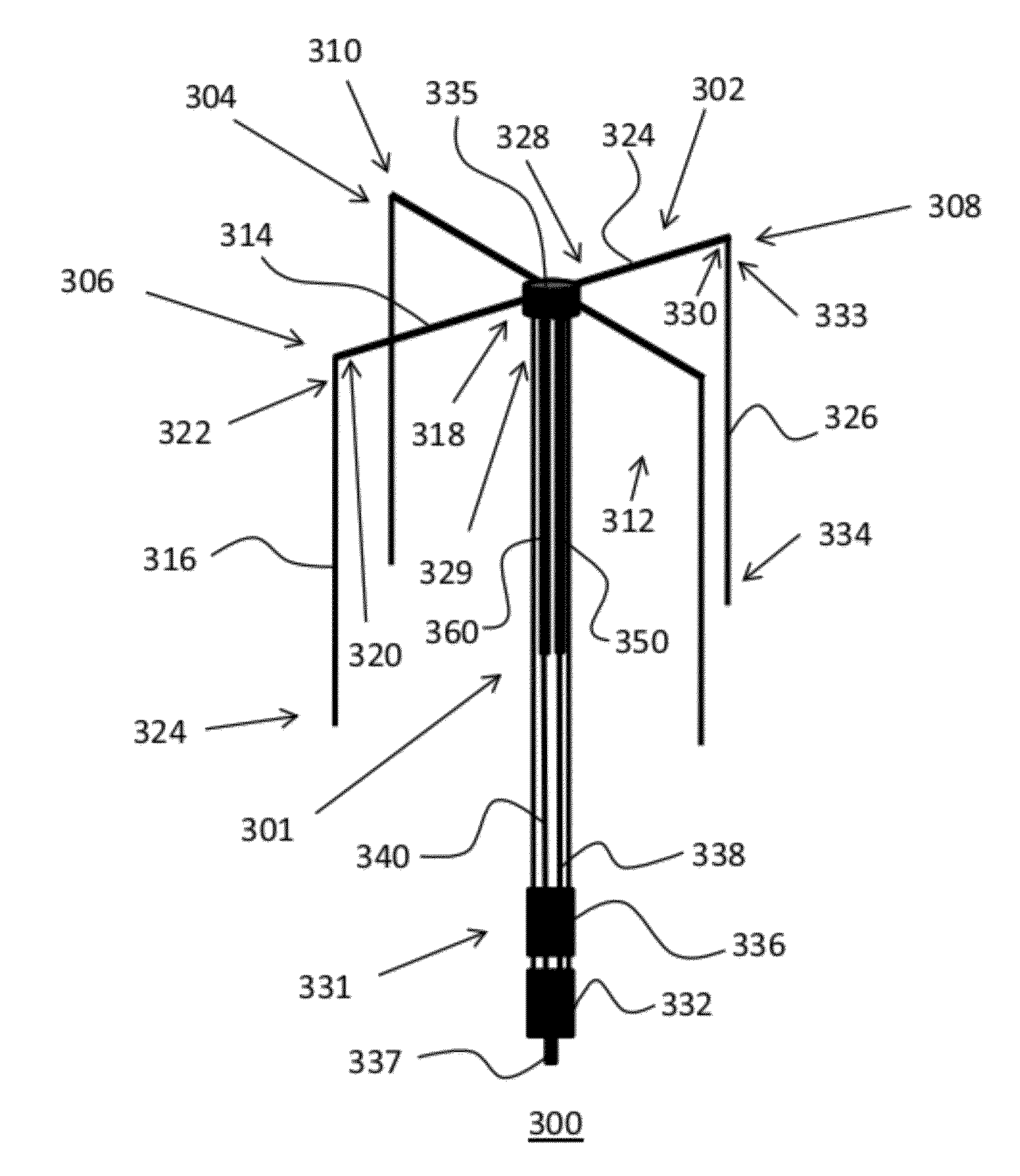
[0053]The present invention, according to an embodiment, overcomes problems with the prior art by providing an antenna assembly with a single connector, that efficiently communicates in simultaneous high-angle and low-angle modes, and is simple and inexpensive to manufacture.

[0054]Described now is an antenna configuration, according to an exemplary embodiment of the present invention. The present invention is a cross polarized SATCOM antenna assembly that includes a set of inverted U-shaped radiating and receiving elements coupled to a...


PUM


Abstract

An antenna assembly includes an antenna/radio interface, a body section connected to the antenna/radio interface, and a group of omnidirectional radiating elements, where each radiating element has a first portion with a first end and a second end, the first end being coupled to the body section and the second end being opposite the first end. Each radiating element also has a second portion with a first end, a second end, and a linear section between the first end and the second end, the first end of the second portion being coupled to the second end of the first portion. The second end of the second portion is opposite the first end of the second linear portion and spaced away from the body section by a distance, arranged so that the first portion of each element is substantially coaxial with the first portion of at least one other of the group of omnidirectional radiating elements, and arranged so that the first portion of each element is substantially orthogonal to the first portion of at least two other of the group of omnidirectional radiating elements, wherein the first portion and the second portion meet at a non-zero angle to each other.

Description

BACKGROUND OF THE INVENTION[0001]1. Field of the Invention[0002]This invention relates in general to satellite-communication (SATCOM) antennas and, more particularly, to a SATCOM antenna that that includes a crossed-dipole element with discrete portions in at least two planes, allowing it to radiate in a broad pattern spanning from high to low angles.[0003]2. Description of the Related Art[0004]Wireless communication is accomplished through use of a radio, which is well known by those having ordinary skill in the art, connected to a radiating element, or antenna, also well know by those having ordinary skill in the art. An antenna is an impedance-matching device used to absorb or radiate electromagnetic waves. The function of the antenna is to “match” the impedance of the propagating medium, which is usually air or free space, to the source.[0005]Antennas are available in many different shapes and sizes. The particular shape and size of an antenna designed for a particular applicati...

Claims


Application Information

Patent Timeline
IPC IPC(8): H01Q21/26
CPCH01Q21/26
Inventor REGALA, FLORENIO PINILI
Owner REGALA FLORENIO PINILI
Why Eureka
Try Eureka