Signal extender system and signal extender thereof

Active Publication Date: 2012-04-05
ATEN INT CO
View PDF9 Cites 11 Cited by
  • Summary
  • Abstract
  • Description
  • Claims
  • Application Information

AI Technical Summary

Benefits of technology

[0013]It is an object of the present invention to provide a signal extender system for transmitting digital multimedia signals between multimedia terminals of a signal source and a signal sink in longer distance.
[0015]It is also an object of the present invention to provide a signal repeater for a signal extender system that can transmit digital multimedia signals between multimedia terminals of a signal source and a signal sink for a longer distance and with fewer signal cables.
[0021]The signal extender system and signal extender thereof according to the present invention are advantageous over existing technologies. It requires only one CAT-5 cable between a TX module and an RX module of the extender system for transmitting HDMI A / V signals by sharing the fourth pair of transmission lines of the single CAT-5 cable with alternating transmission of the BD differential signals and a partial differential clock signal, and utilizes a timing memory unit to memorize the partial differential clock signal and continuously replicate the partial differential clock signal to revert the complete differential clock signal for output to the sink. This significantly simplifies the extender system and reduces the costs for HDMI A / V signal transmission. In addition, it provides a quick and easy way to extend the distance of HDMI A / V signal transmission by providing a series of repeaters between the TX and Rx modules of the extender system.

Problems solved by technology

The major limitation of this arrangement is the short distance between the source 110 and sink 120, as HDMI cables are usually very bulky and expansive and only made in a length of a few feet.
However, there are still major limitations with this arrangement.
First, the transmission distance is still relatively short.
In addition, the I2C is a bi-directional signal not suitable to be carried by the one-way differential data signal.

Method used


Image

  • Signal extender system and signal extender thereof
  • Signal extender system and signal extender thereof
  • Signal extender system and signal extender thereof

Examples


Embodiment Construction

[0036]As required, a detailed illustrative embodiment of the present invention is disclosed herein. However, techniques, systems and operating structures in accordance with the present invention may be embodied in a wide variety of forms and modes, some of which may be quite different from those in the disclosed embodiment. Consequently, the specific structural and functional details disclosed herein are merely representative, yet in that regard, they are deemed to afford the best embodiment for purposes of disclosure and to provide a basis for the claims herein, which define the scope of the present invention. The following presents a detailed description of the preferred embodiment (as well as other alternative embodiments) of the present invention.

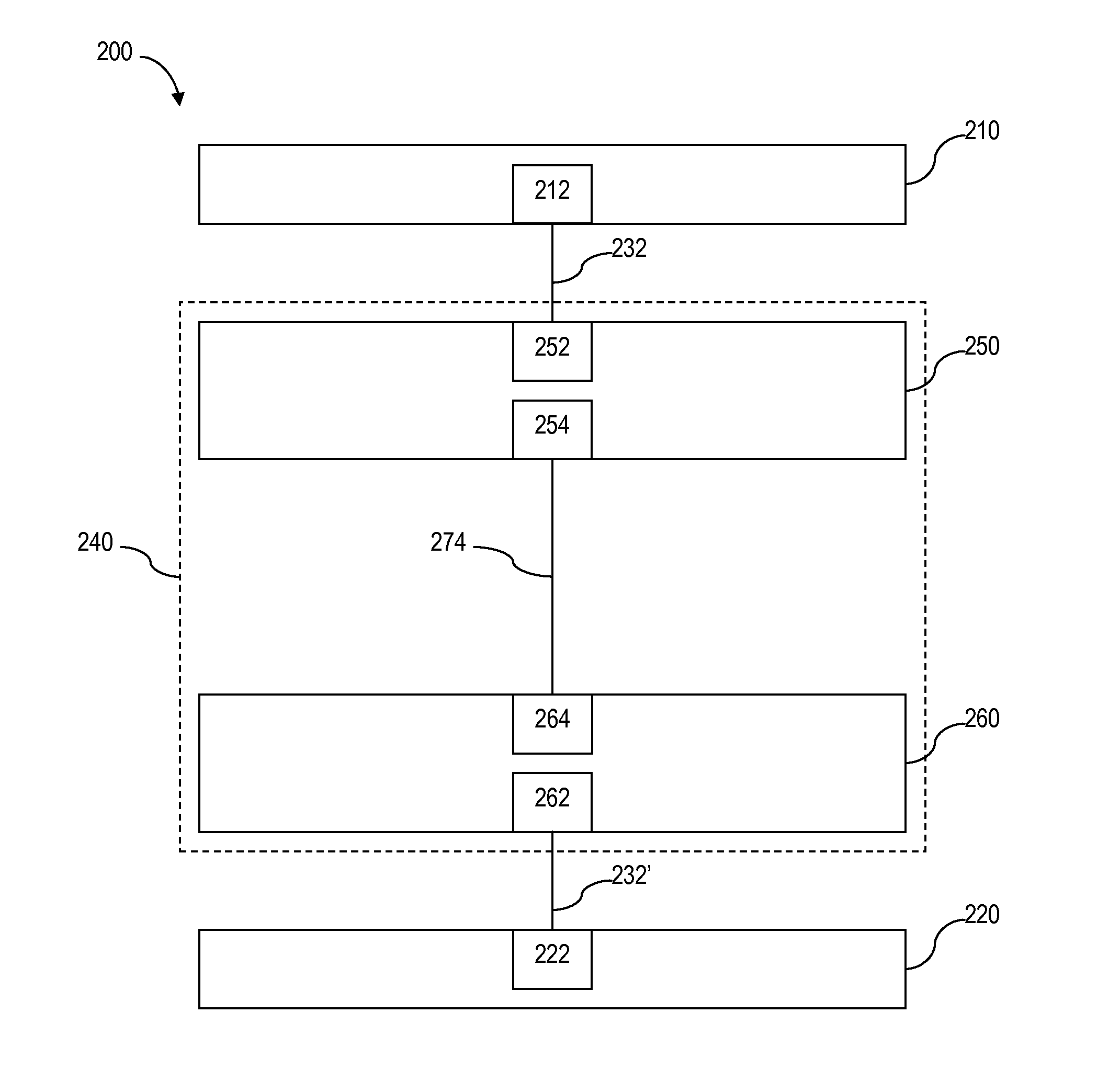
[0037]Referring to FIG. 2, there is shown at 200 an embodiment of the signal extender system for transmitting digital multimedia signals between a source 210 and a sink 220. The digital multimedia signals can be, but not limited to, dig...


PUM


Abstract

A signal extender system including a first electronic apparatus, a second electronic apparatus, and a signal extender. The signal extender system includes a transmission module, a receiving module, and pairs of differential transmission lines. The receiving module includes a timing memory unit. The transmission module receives a digital image differential signal including differential data signals, a differential timing signal, and a two-way differential signal. A first pair of differential transmission lines, a second pair of differential transmission lines, and a third pair of differential transmission lines of the pairs of differential transmission lines transmit the differential data signals respectively. A fourth pair of differential transmission lines alternately transmits the two-way differential signal and a part of differential timing signal. The timing memory unit memories and continually replicates the part of differential timing signal to recover the differential timing signal and output it to the second electronic apparatus.

Description

BACKGROUND OF THE INVENTION[0001]1. Field of the Invention[0002]This invention relates to digital data signal transmission, and in particular, it relates to a signal extender system for transmitting digital data signals with a single cable.[0003]2. Description of the Related Art[0004]In recent years, with the constant evolution of electronic technology, multimedia audio-visual (A / V) technology has developed very rapidly. One example is the High Definition Multimedia Interface (HDMI) used for integrated A / V signal transmission. Since a single HDMI cable can be used for transmitting non-compressed audio signals and high resolution video signals, there is no need to convert analog into digital (A / D) signals or digital into an analog signal (D / A), so the A / V signals can be transmitted without distortion.[0005]Referring to FIG. 1a, there is shown at 100 a typical conventional arrangement for transmitting A / V signals between a signal source device 110 and a signal sink (target) device 120...

Claims


Application Information

Patent Timeline
IPC IPC(8): H04L7/04H04L27/00
CPCH04L7/0008H04L7/0083H04L1/1854
Inventor HSUEH, CHAO-HSUAN
Owner ATEN INT CO
Why Eureka
Try Eureka