Method, device and system for optical network switching protection

Active Publication Date: 2012-04-05
HUAWEI TECH CO LTD
View PDF3 Cites 13 Cited by
  • Summary
  • Abstract
  • Description
  • Claims
  • Application Information

AI Technical Summary

Benefits of technology

[0022]In the method, the device and the system for optical network switching protection according to the embodiments of the present disclosure, after a service is switched to the standby optical central office end apparatus due to a fault of the backbone optical fibre or a fault of the active optical central office end apparatus, first, the ranging optical terminal apparatus is selected, the delay difference between the delay from the selected ranging optical terminal apparatus to the standby optical central office end apparatus and the delay from the ranging optical terminal apparatus to the active optical central office end apparatus is obtained, and then the time at which the data sent by all the optical terminal apparatuses reaches the standby optical central office end apparatus is synchronized according to the delay differe

Problems solved by technology

In the PON fault protection procedure, the inventor finds that the following problems exist in the current PON fault protection.
If many ONUs access an OLT in a PON, service interruption time

Method used


Image

  • Method, device and system for optical network switching protection
  • Method, device and system for optical network switching protection
  • Method, device and system for optical network switching protection

Examples


embodiment 1

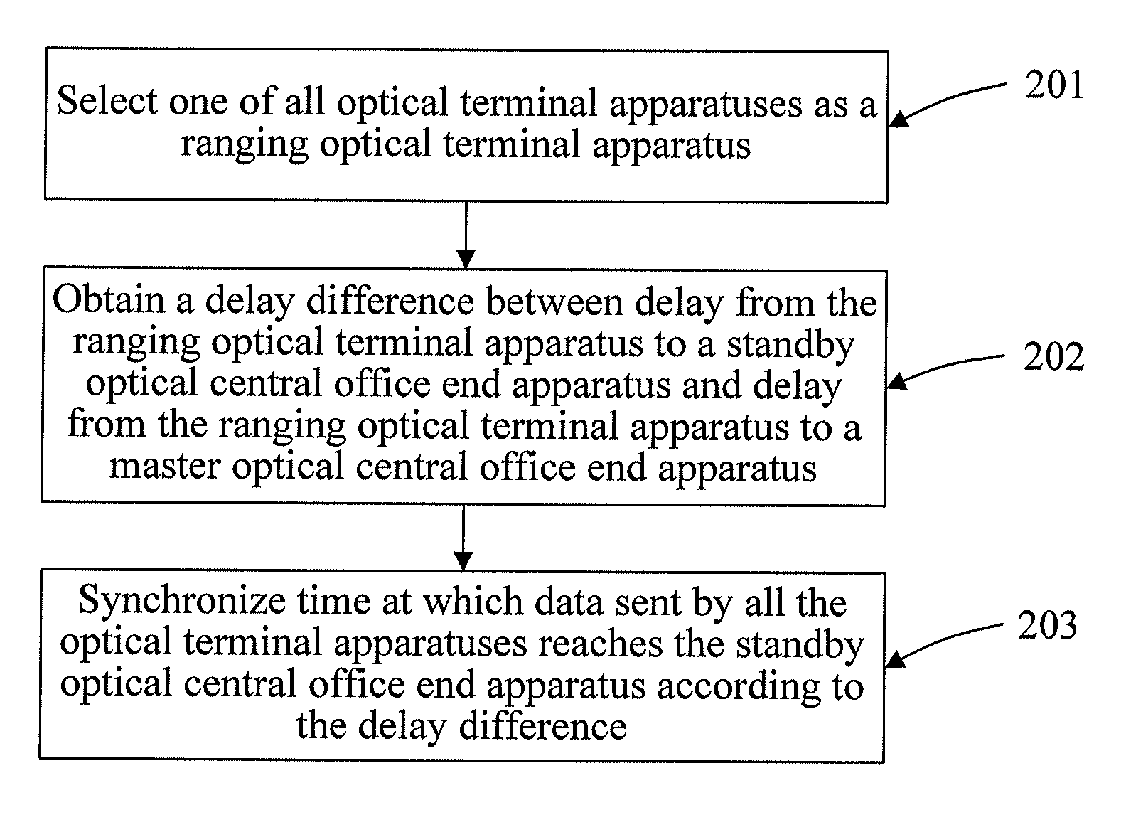
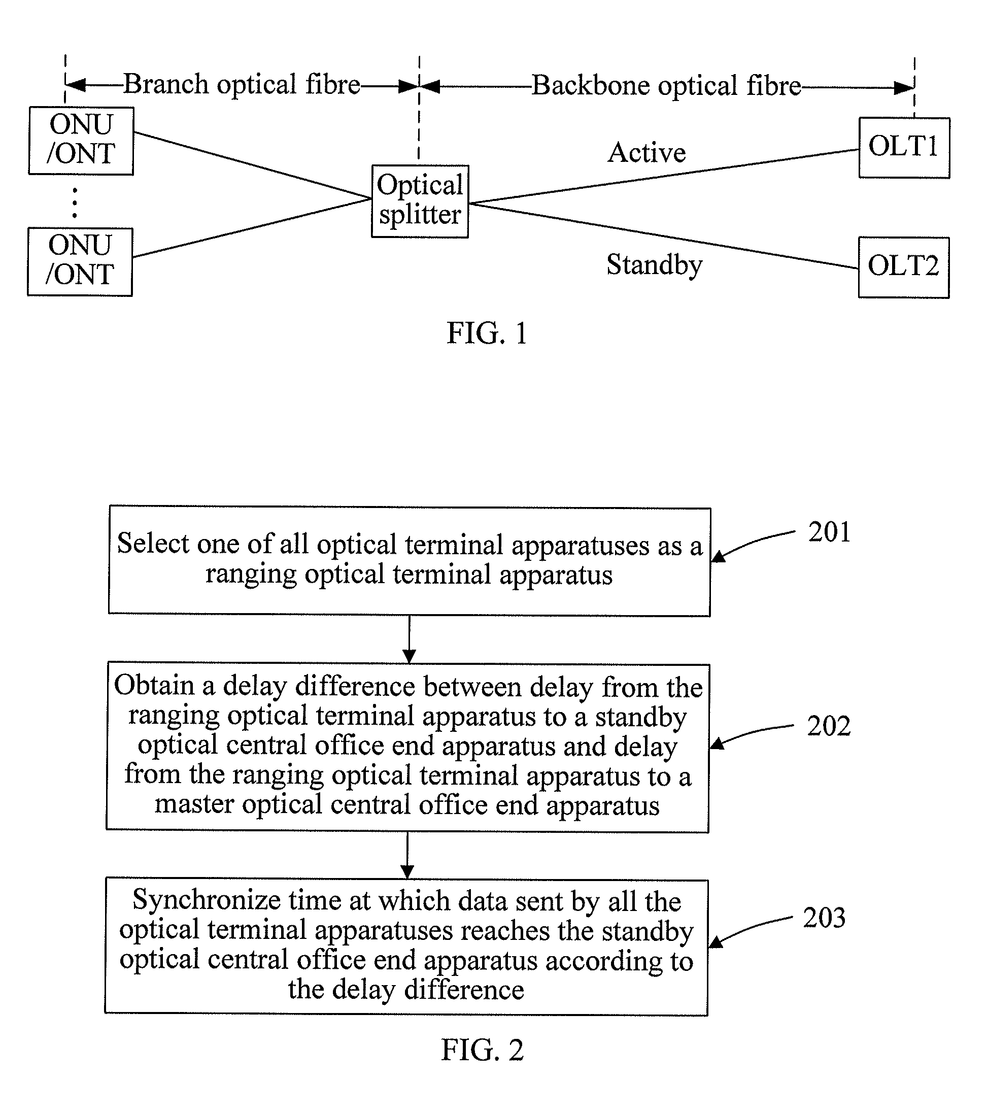
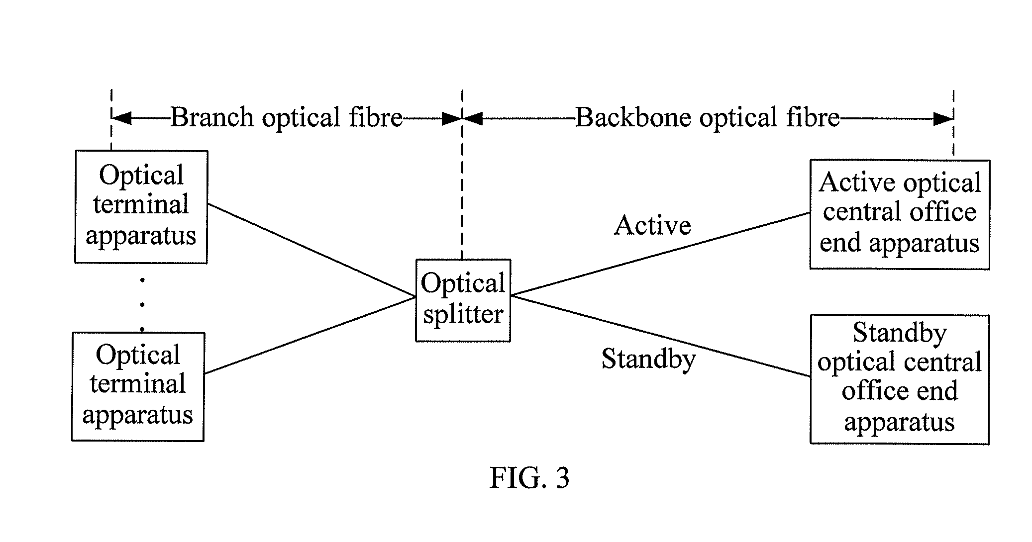
[0040]This embodiment provides a method for optical network switching protection. After a service is switched from an active OLT to a standby OLT, the standby OLT selects a special ONU (referred to as a ranging ONU) from ONUs, and obtains first Rtd of the ranging ONU under the active OLT and second Rtd of the ranging ONU under the standby OLT; and then obtains an Rtd difference ΔRtd according to the first Rtd and the second Rtd of the ranging ONU, and delivers the ΔRtd to all the ONUs in a multicast / broadcast manner, so that the ONUs each calculate EqD under the standby OLT. Definitely, in the protection method of this embodiment, the standby OLT may further calculate second EqD of the ranging ONU under the standby OLT after detecting the second Rtd; and finally calculate an EqD difference ΔEqD, and deliver the ΔEqD to all the ONUs in a multicast / broadcast manner, so that the ONUs each calculate the EqD under the standby OLT.

[0041]In order to enable each ONU to calculate the EqD und...

embodiment 2

[0071]This embodiment provides a method for optical network switching protection. After a service is switched from an active OLT to a standby OLT, the standby OLT first selects a special ONU (referred to as a ranging ONU) from ONUs, and obtains first Rtd of the ranging ONU under the active OLT and second Rtd of the ranging ONU under the standby OLT; and then obtains an Rtd difference ΔRtd according to the first Rtd and the second Rtd of the ranging ONU, and instructs all the ONUs to maintain the original EqD unchanged in a multicast / broadcast / unicast manner. The standby OLT adjusts start time of an uplink frame header of each ONU according to the ΔRtd. Definitely, in the protection method of this embodiment, the standby OLT may further calculate second EqD of the ranging ONU under the standby OLT after detecting the second Rtd; and finally calculate an EqD difference ΔEqD, and instruct all the ONUs to maintain the original EqD unchanged in a multicast / broadcast / unicast manner. The s...

embodiment 3

[0104]This embodiment provides a method for optical network switching protection. After a service is switched from an active OLT to a standby OLT, the standby OLT first selects a special ONU (referred to as a ranging ONU) from ONUs, and obtains first Rtd of the ranging ONU under the active OLT and second Rtd of the ranging ONU under the standby OLT; then obtains an Rtd difference ΔRtd according to the first Rtd and the second Rtd of the ranging ONU, and obtains first Rtd of each ONU under the active OLT; and subsequently, calculates second EqD of each ONU under the standby OLT according to the first Rtd and ΔRtd, in which the calculation formula is: second Teqd−(first Rtd−ΔRtd). The second Teqd is a constant value, and is an Rtd value under the standby OLT when EqD=0, that is, an Rtd value of the furthest ONU under the standby OLT. The finally calculated second EqD is delivered to each ONU in a multicast / broadcast manner.

[0105]Specifically, referring to FIG. 6, the active OLT, the s...


PUM


Abstract

In the field of optical communications technologies, a method and a system for optical network switching protection are provided, to solve the problem of long service interruption time during active-standby switching in the prior art. One optical terminal apparatus is selected as a ranging optical terminal apparatus after a service is switched from an active optical central office end apparatus to a standby optical central office end apparatus; a delay difference between delay from the ranging optical terminal apparatus to the standby optical central office end apparatus and delay from the ranging optical terminal apparatus to the active optical central office end apparatus respectively is obtained; and time at which data sent by all the optical terminal apparatuses reaches the standby optical central office end apparatus is synchronized according to the delay difference. The method and the system are mainly used in an optical communication system.

Description

CROSS-REFERENCE TO THE RELATED APPLICATIONS[0001]This application is a continuation of International Application No. PCT / CN2009 / 073532, filed on Aug. 26, 2009, which is hereby incorporated by reference in its entirety.FIELD[0002]The present disclosure relates to the field of optical communications technologies, and in particular, to a method, a device and a system for optical network switching protection.BACKGROUND[0003]As shown in FIG. 1, a Passive Optical Network (PON) is mainly formed of Optical Line Terminations (OLTs), an optical splitter, Optical Network Units (ONUs) / Optical Network Terminals (ONTs) and optical fibres for connecting these apparatuses. Each OLT, as a central office end apparatus, is connected to the optical splitter through a backbone optical fibre, and the optical splitter is connected to each ONU through a single branch optical fibre. The PON supports fault protection for the backbone optical fibre and the OLT apparatus, and as shown in FIG. 1, two OLT appara...

Claims


Application Information

Patent Timeline
IPC IPC(8): H04J14/00H04B17/00
CPCH04J3/0682H04L43/0852H04J14/0283H04Q2011/0079H04Q2011/0081H04Q11/0067
Inventor ZHENG, RUOBIN
Owner HUAWEI TECH CO LTD
Why Eureka
Try Eureka