Mechanical draft systems

a mechanical draft and control device technology, applied in combustion control, failure to operate, combustion failure safe, etc., can solve problems such as unnecessarily duplicated components and functions, unnecessary coordination among the various controllers, and complicated coordination between the various controllers

Inactive Publication Date: 2012-04-05
ENERVEX
View PDF7 Cites 25 Cited by
  • Summary
  • Abstract
  • Description
  • Claims
  • Application Information

AI Technical Summary

Problems solved by technology

The control device may also affect a furnace shut down procedure during unstable conditions.
With the large number of control devices in the mechanical room providing various functions, coordination among the various controllers can be quite complex.
Furthermore, in this regard, components and functions can be unnecessarily duplicated.
However, until now, greater processor functionality has yet to be achieved for simplifying the installation and control of mechanical draft systems.
Because of this deficiency, correcting any problems after installation becomes much more difficult.
One concern that has been identified regarding conventional mechanical draft systems is their lack of intelligent processing functionality for controlling furnaces or boilers during less than optimal conditions.
This all-or-nothing approach can result in a number of machines sitting idly during times of great need.
Therefore, a void exists in the prior art for allowing a system to operate in a low output state during less than optimal conditions and to operate in such conditions without compromising safety and efficiency.
Conventional mechanical draft systems may also present challenging installation and / or reconfiguration scenarios.
Thus, physical obstructions may exist requiring cabling between the controller and related equipment be run for even longer distances or in inconvenient locations.
Another concern with conventional mechanical draft systems is the lack of remote access to the pressure controller.
Yet another problem not addressed by conventional mechanical draft systems is the lack of programmable appliance sequencing.
For example, conventional draft systems are not programmable to prioritize the use of specific appliances to meet a demand based on predefined, and programmable, conditions.

Method used


Image

  • Mechanical draft systems
  • Mechanical draft systems
  • Mechanical draft systems

Examples


Embodiment Construction

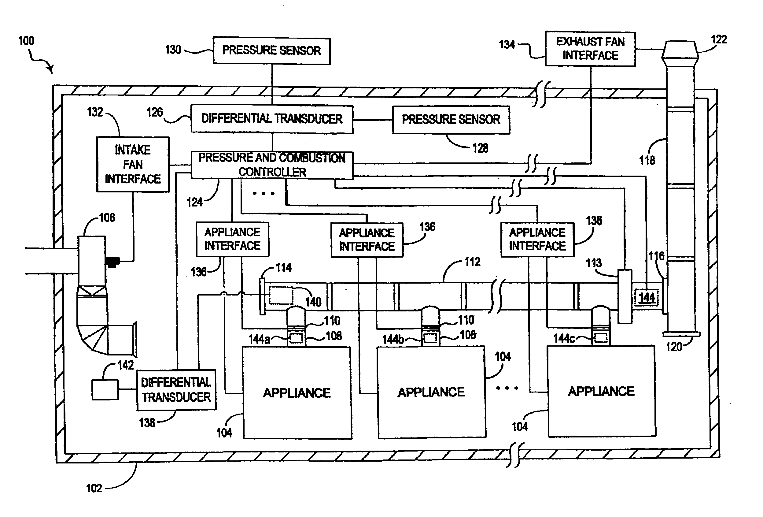
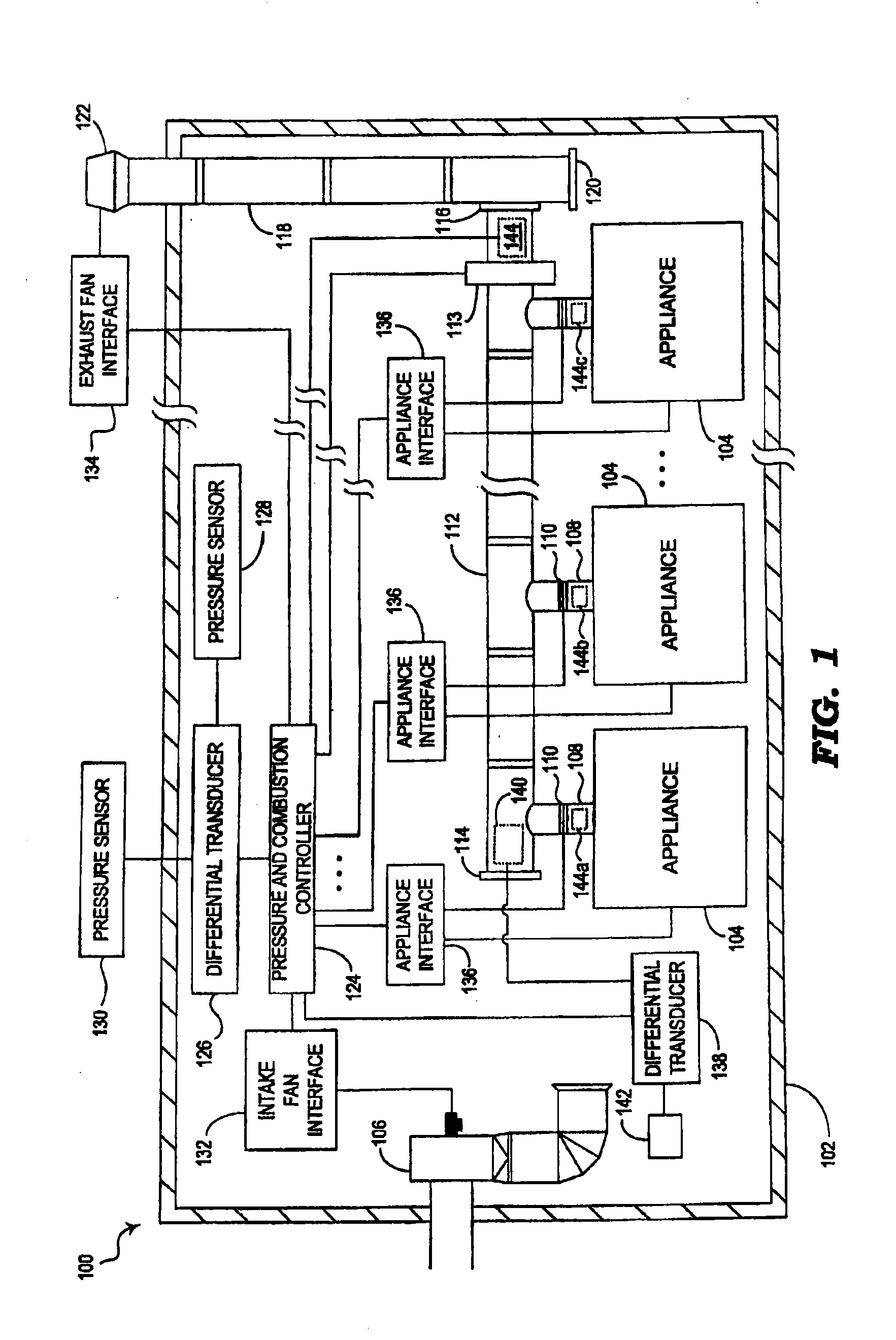
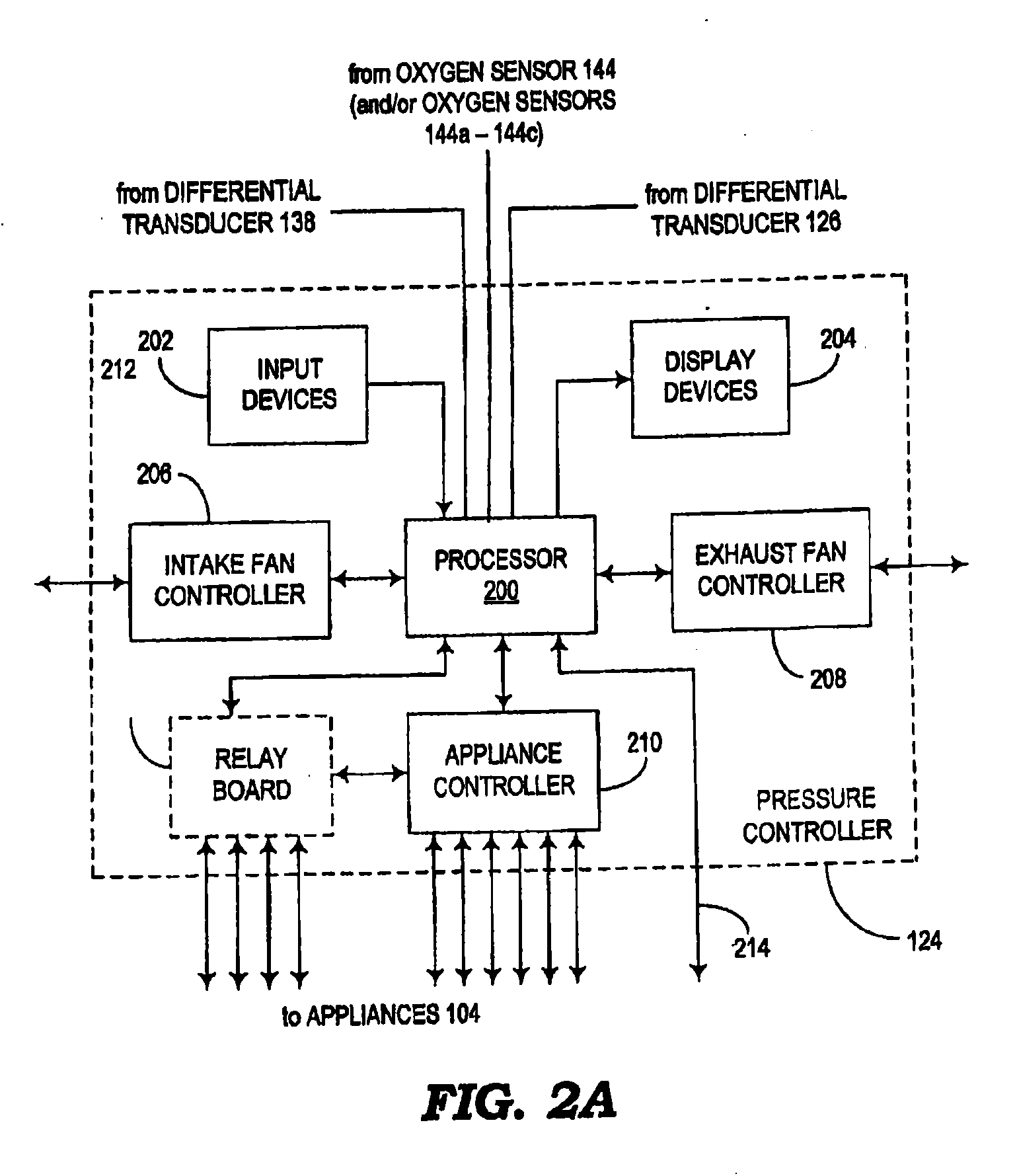
[0033]Fan assemblies, mechanical draft systems and methods are provided. In some embodiments, combustion air is drawn into a mechanical room and supplied to combustion or heating devices and air exhausted from the combustion or heating devices is vented from the mechanical room into the atmosphere. Some embodiments of the controllers are capable of controlling the on / off state and speed of intake fans and exhaust fans and can also control any number of appliances, such as furnaces or boilers, within the system. The unitary controllers disclosed herein may be configured using microprocessor elements or other suitable electrical components for providing greater functionality than conventional exhaust system controllers. Also, the controllers can be programmed in the field and reprogrammed as desired allowing greater flexibility.

[0034]The controllers can be initialized during the installation or set-up of the mechanical draft system. The initialization process involves entering informa...


PUM


Abstract

A representative mechanical draft system for drawing exhaust gasses from a chimney includes: an exhaust fan assembly having: a housing defining a chamber and having opposing openings, the opposing openings having a centerline extending therebetween, a first of the openings being operative to intake a flow of gasses, a second of the openings being operative to exhaust the flow of gasses from the chamber; and a centrifugal fan having a motor and an impeller, the motor being mounted external to the housing, the impeller being positioned within the chamber, a rotational axis of the impeller being inclined with respect to the centerline extending between the openings of the housing.

Description

CROSS-REFERENCE TO RELATED APPLICATIONS[0001]This application is a continuation-in-part application of co-pending U.S. patent application Ser. No. 12 / 434,850, filed May 4, 2009, and entitled “Fan Assemblies, Mechanical Draft Systems and Methods,” which claims the benefit (as is a continuation-in-part application) of U.S. patent application Ser. No. 10 / 712,516, filed Nov. 13, 2003, and entitled “Pressure Controller for a Mechanical Draft System” (now U.S. Pat. No. 7,275,533), which claims the benefit of U.S. provisional application No. 60 / 453,086, filed on Mar. 6, 2003, and entitled “Systems and Methods Involving Modulating Pressure Controls,” and U.S. provisional application No. 61 / 434,210, filed Jan. 19, 2011, and entitled “True Inline Centrifugal Power Venter With / Without Boiler Flue Gas Economizer” with each of the above-mentioned disclosures being incorporated by reference in their entireties into the present disclosure.TECHNICAL FIELD[0002]The present disclosure generally relat...

Claims


Application Information

Patent Timeline
Patent Type & Authority Applications(United States)
IPC IPC(8): F23L17/02F04D27/00F28F27/02
CPCF23J11/02F23N2037/20F23L11/00F23L17/005F23N3/002F23N5/18F23N5/203F23N5/242F23N2025/06F23N2031/28F23N2033/04F23N2033/08F23N2035/04F23N2035/06F23L5/02F23N2225/06F23N2231/28F23N2233/04F23N2235/04F23N2237/20F23N2233/08F23N2235/06
Inventor HAGENSEN, STEENHAN, YOUNG KYU
Owner ENERVEX
Why Eureka
Try Eureka