Energy monitoring device and control method therefor, and energy monitoring program

a technology of energy monitoring and control method, applied in the direction of programme control, total factory control, instruments, etc., can solve the problems of operating type waste, unproductive period where no added value is created in an operating cycle, etc., and achieve the effect of easy detection of single-cycle time-series data

Active Publication Date: 2012-04-05
ORMON CORP
View PDF20 Cites 24 Cited by
  • Summary
  • Abstract
  • Description
  • Claims
  • Application Information

AI Technical Summary

Benefits of technology

[0035]In this case, a frequency component of a single-cycle that is equal to or close to the fundamental ...

Problems solved by technology

On the other hand, an unproductive period where no added-value is created in an operating cycle ti...

Method used


Image

  • Energy monitoring device and control method therefor, and energy monitoring program
  • Energy monitoring device and control method therefor, and energy monitoring program
  • Energy monitoring device and control method therefor, and energy monitoring program

Examples


first embodiment

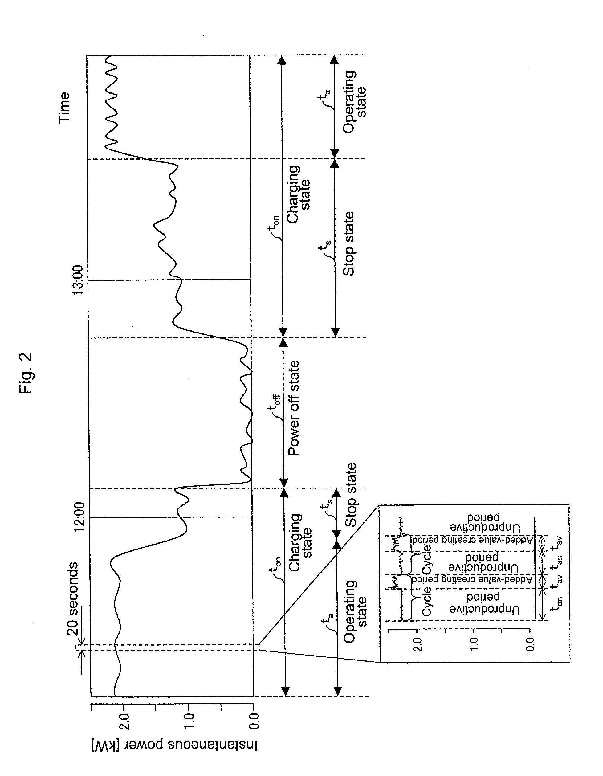
[0069]An embodiment of the present invention is described referring to FIGS. 1-7. Prior to describing the present embodiment, a device status and an amount of energy to be improved computed by the present embodiment are explained referring to FIG. 2.

[0070]FIG. 2 is a graph showing operating-status of a press machine, more specifically, a graph of varying instantaneous electric power (kW) over time that is consumed by the press machine. Top of FIG. 2 shows a graph that covers a couple of hours, in which one portion of the graph is magnified. In the bottom of FIG. 2, the magnified portion shows 20 seconds worth data. In FIG. 2, the press machine is used as an example, however, the device is not limited to the press machine and other devices may be used.

[0071]In the top of FIG. 2, a period toff having an instantaneous electric power close to 0 kW is a period when the press machine is turned off and is referred to as a power off state. On the other hand, a period ton, which excludes the...

second embodiment

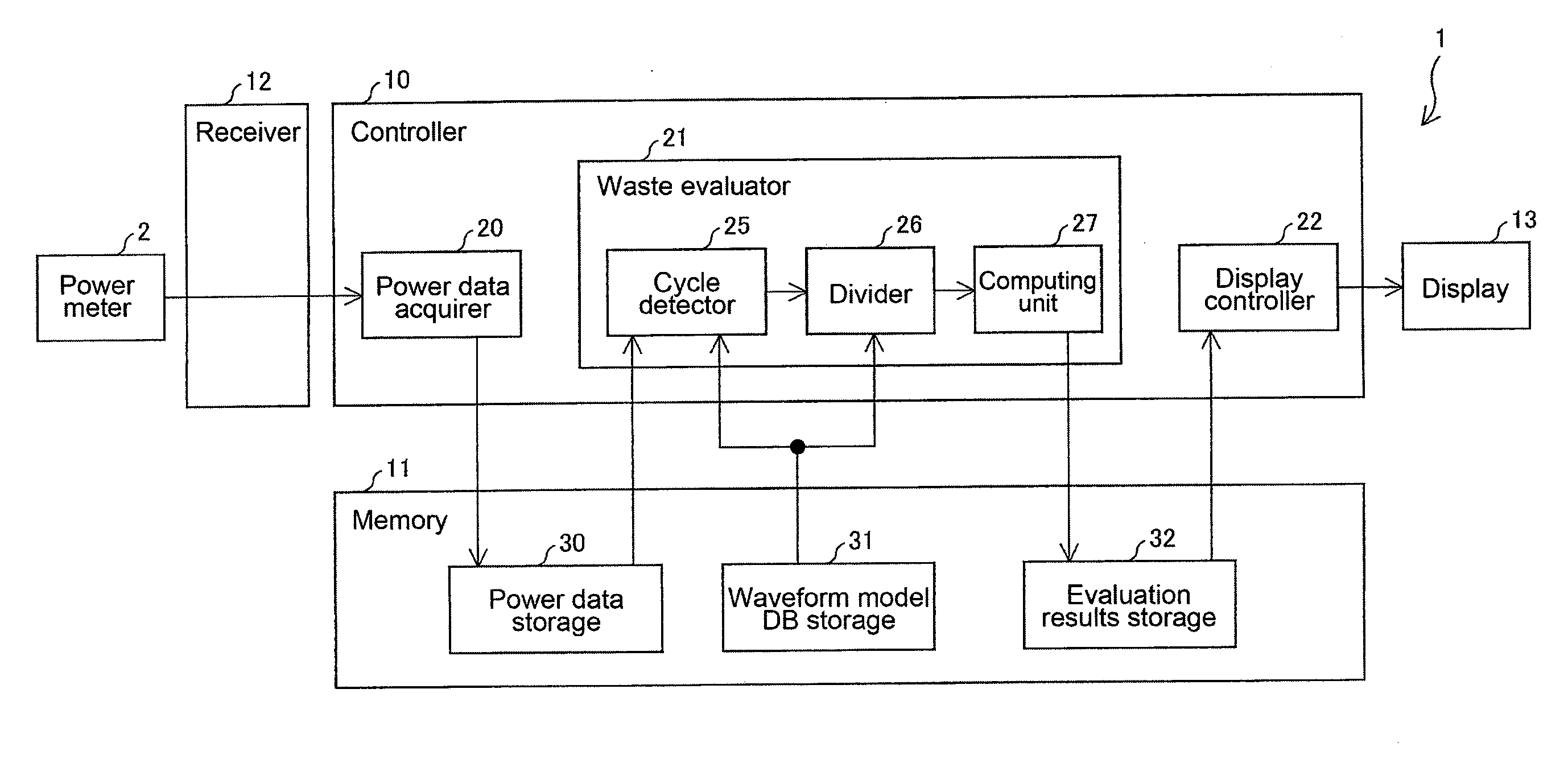
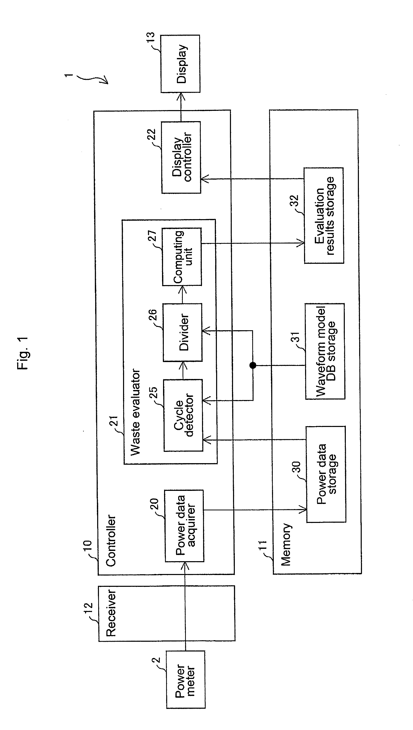
[0118]Next, another embodiment of the present invention is described referring to FIGS. 8 and 9. Compared to the energy monitoring system 5 shown in FIGS. 1˜7, an energy monitoring system 5 of the present embodiment includes an additional component that creates a waveform model DB to be stored in the waveform model DB storage 31.

[0119]Compared to the energy monitoring system 5 shown in FIGS. 1˜7, the energy monitoring system 5 of the present embodiment newly implements a PLC 4 to uniformly control the operations of the processing machine 3. An input unit 14 is newly added to an energy monitoring device 1, and a detected data acquirer 50 and a model DB creator 51 are newly installed in the controller 10 of the energy monitoring device 1. Components having the same functions described previously are labeled by the same numerical references and descriptions of these components are omitted.

[0120]In the processing machine 3, such as a press machine, a control device sends a single-cycle ...

third embodiment

[0137]Next, another embodiment of the present invention is described referring to FIGS. 11˜17. An energy monitoring system 5 of the present embodiment includes a cycle detector 25 whose function is different from the energy monitoring system 5 shown in FIGS. 1˜7. Components having the same functions as described previously are labeled by the same numerical references, and descriptions of these components are omitted.

[0138]The cycle detector 25 of the present embodiment detects single-cycle power data by detecting a start-point of the single-cycle from the power data using a design cycle-time value Dct and a frequency analysis. Here, the design cycle-time value Dct refers to a planned value of cycle time defined by a responsible person at the manufacturing site.

[0139]FIG. 11 shows a schematic configuration of cycle detector 25 and a memory that stores data used for the cycle detector 25. As shown in the figure, the cycle detector 25 is configured to include a frequency analyzer 110; ...


PUM


Abstract

A processing machine processes a work and repeats processes on the work, thereby consuming energy. Within the consumed energy, room for improvement is computed by an energy monitoring device and is referred to as an amount of energy that can be improved. An energy monitoring device includes a power data acquirer that acquires a time-series power data measured by a power meter, a cycle detector that detects a single-cycle power data from the power data acquired by the acquirer, a divider that divides the single-cycle power data detected by the detector into an added-value creating portion and an unproductive portion, and a computing unit that computes an amount of energy consumed in the unproductive portion divided by the divider and defines it as the amount of energy to be improved.

Description

CROSS-REFERENCE TO RELATED APPLICATIONS[0001]This is a continuation application of PCT / JP / 2010 / 001401 filed Mar. 2, 2010, designating the United States of America, the disclosure of which, including the specification, drawings, and claims, is incorporated by reference in its entirety. The disclosure Japanese Patent Application No. 2009-096319 filed on Apr. 10, 2009, including the specification, drawings, and claims is expressly incorporated by reference in its entirety.TECHNICAL FIELD[0002]The present invention relates to an energy monitoring device, a method of controlling the energy monitoring device, and an energy monitoring program, in which the energy monitoring device computes an amount of energy to be improved within an energy consumed by a processing machine executing processes. Specifically, the present invention relates to an energy monitoring device and the like that computes an amount of energy that may be reduced, in which the processing machine processes a manufacturin...

Claims


Application Information

Patent Timeline
IPC IPC(8): G01R21/00G06F19/00
CPCG05B23/0283G05B15/02G05B19/40938G05B2219/49092Y02P90/02
Inventor KITAGAWA, SHINTAROTATEISHI, TAISUKEYAMAMURA, KENJISAITO, HIROSHIENDO, MAKINAKASHIMA, CHISATO
Owner ORMON CORP
Why Eureka
Try Eureka