Groutless tile system and method for making the same

a groutless tile and tile technology, applied in the field of floor and wall covering tiles, can solve the problems of laborious grouting step, high labor intensity of grouting step, and extremely tedious process, and achieve the effects of reducing weight and/or cost, and improving mechanical properties and/or performance benefits

Inactive Publication Date: 2012-04-12
MOHAWK CARPET
View PDF7 Cites 4 Cited by
  • Summary
  • Abstract
  • Description
  • Claims
  • Application Information

AI Technical Summary

Benefits of technology

[0021]Additionally disclosed herein is a composite groutless tile with improved mechanical properties and/or performance benefits when compared to conventional ceramic tile. In some embodiments, the composite groutless tile used in a groutless tile system comprises a ceramic tile encapsulated in a polymer, wherein at least a portion of the polymer can be removed, e.g. milled, to produce a tongue and groove interlocking profile for use in the groutless tile system. In an embodiment, the polymer is disposed directly on a surface of the tile.
[0022]Further disclosed herein is a groutless tile using a substrate with a modified polymer matrix. The modified polymer matrix comprises a first polymer and comprises a lower a...

Problems solved by technology

This step of grouting the tiles is labor intensive and represents a significant portion of the labor involved in a typical tile installation.
Due to the time and labor involved in tile installation, it is typically quite costly to have tile professionally installed.
Unfortunately, this is an extremely tedious process, and many homeowners do not wish to spend the time necessary for a satisfactory installation.
While this system is easier to install than traditional tiles, it still requires a separate grout to be applied and uses a laminate material rather than a solid tile.
A laminate material is not likely to be...

Method used


Image

  • Groutless tile system and method for making the same
  • Groutless tile system and method for making the same
  • Groutless tile system and method for making the same

Examples


Embodiment Construction

[0039]As used herein, the term “disposed” generally means located either at or upon. Additionally, the term disposed is intended to include an element integrally or detachably connected to another element as well as object simple placed on another element. Furthermore, it will be understood that when an element is referred to as being “disposed on” another element, it can be directly on the other element or intervening elements may be present there between. In contrast, when an element is referred to as being “disposed directly on” another element, there are no intervening elements present.

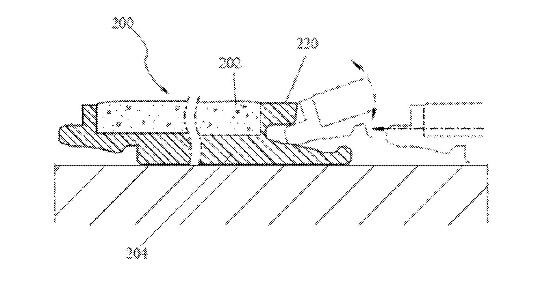
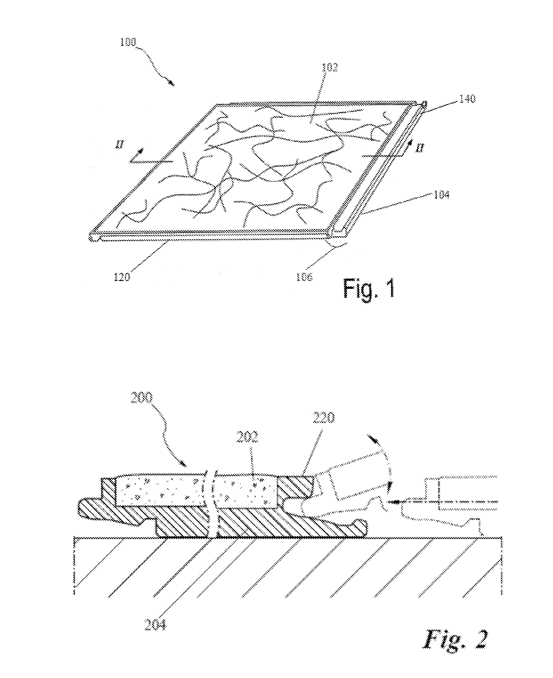
[0040]Referring now to FIG. 1, a groutless tile in accordance with an exemplary embodiment of the present invention is generally depicted as 100. The groutless tile 100 includes a durable surface 102 that is disposed on a substrate 104. In exemplary embodiments, the durable surface 102 may be affixed to the substrate 104 using a wide variety of methods such as the use of an adhesive. The durable s...


PUM

PropertyMeasurementUnit
Fractionaaaaaaaaaa
Fractionaaaaaaaaaa
Fractionaaaaaaaaaa

Abstract

A groutless tile system including groutless tiles, wherein each groutless tile includes a substrate, a durable surface disposed within a groove defined by the substrate, the durable surface having bottom surface, and a first coupling member disposed on an edge of the substrate. The first coupling member comprises a first bendable portion and a groove, the groove having an upper surface and a lower surface. The bottom surface of the durable surface is substantially coplanar with a point between the upper and lower surfaces of the groove. The polymer matrix forming at least a portion of the substrate can be modified to reduce the weight of the groutless tile or the cost to manufacture the groutless tile. In some embodiments, the polymer matrix is modified through the use of gas nucleation or a blowing agent.

Description

CROSS-REFERENCE TO RELATED APPLICATION & PRIORITY CLAIM[0001]This application is a continuation-in-part of U.S. patent application Ser. No. 13 / 186,989, filed Jul. 20, 2011, and entitled “Groutless Tile System And Method For Making The Same,” which is a divisional of U.S. patent application Ser. No. 11 / 701,777, filed Feb. 2, 2007, and entitled “Groutless Tile System And Method For Making The Same,” which are incorporated herein by reference in their entirety as if fully set forth below.BACKGROUND OF THE INVENTION[0002]1. Field of the Invention[0003]The present invention relates generally to floor and wall covering tiles. More particularly, it relates to a tile system that does not require a grout compound to be applied to the tiles after installation.[0004]2. Description of Related Art[0005]Ceramic tiles are widely used as a floor and wall covering in both residential and commercial applications. Tile is very versatile, and has been in use as a floor and wall covering for centuries. ...

Claims


Application Information

Patent Timeline
IPC IPC(8): E04C2/38B29C45/14E04C2/20
CPCE04F13/14E04F15/087E04F2201/0161E04F2201/0153E04F2201/0146E04F2201/0115
Inventor EARL, DAVIDALFORD, TOMPATKI, RAHULKING, WESLEYCAPPELLE, MARK
Owner MOHAWK CARPET
Why Eureka
Try Eureka