
Machine for application of caps on containers such as bottles and the like

a machine and container technology, applied in the direction of caps, caps, closures using caps, etc., can solve the problems of reducing the service life of the machine, so as to avoid the stress of the gripper and its pins, and avoid the risk of damage to the container

Inactive Publication Date: 2012-04-12
AROL
View PDF4 Cites 12 Cited by
  • Summary
  • Abstract
  • Description
  • Claims
  • Application Information

AI Technical Summary

Benefits of technology

[0012]The object of the present invention is to provide a machine for application of threaded or non-pre-threaded caps on containers that will avoid the risk of damage to the containers and that will avoid stressing of the grippers and their pins.
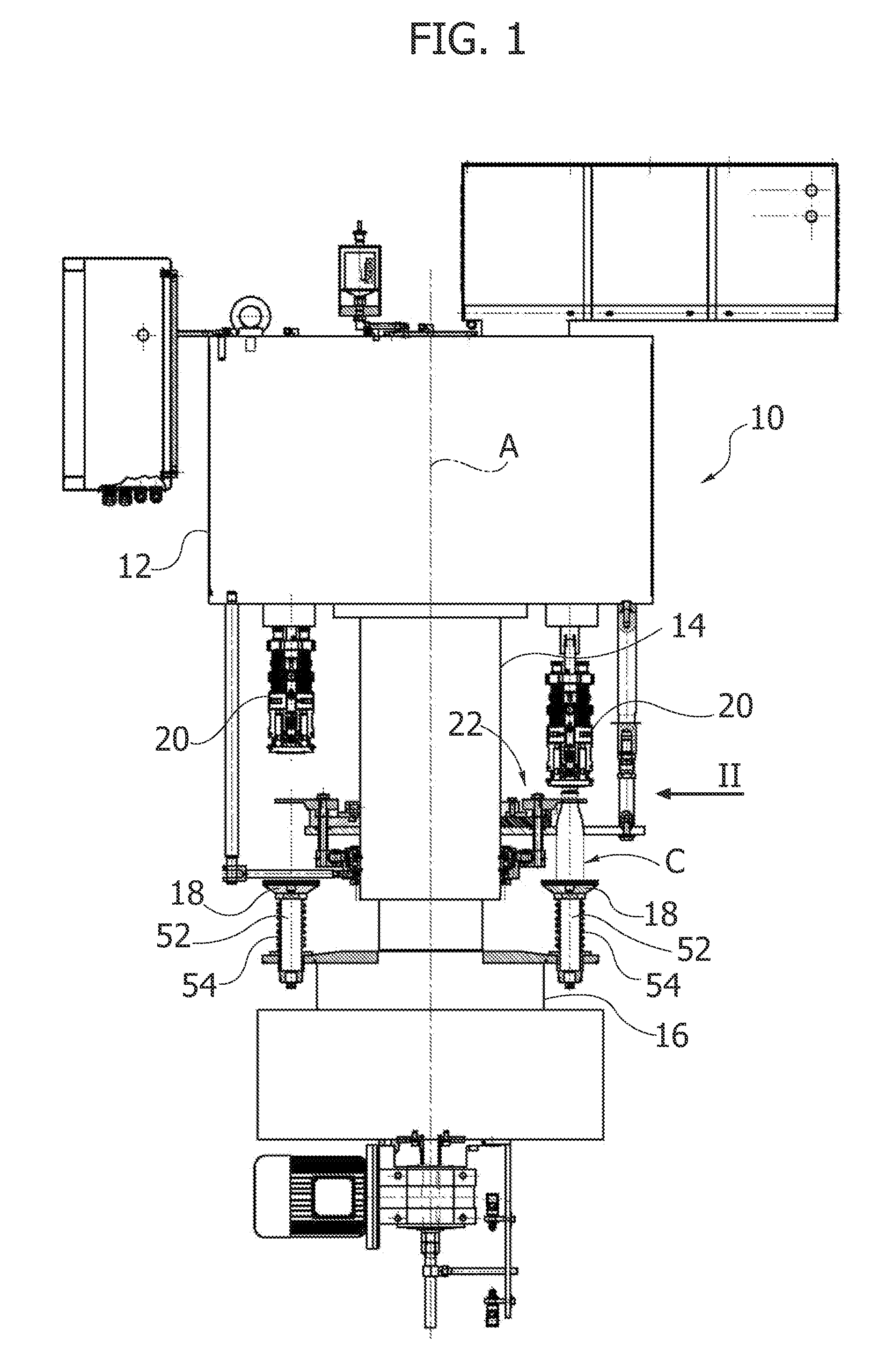
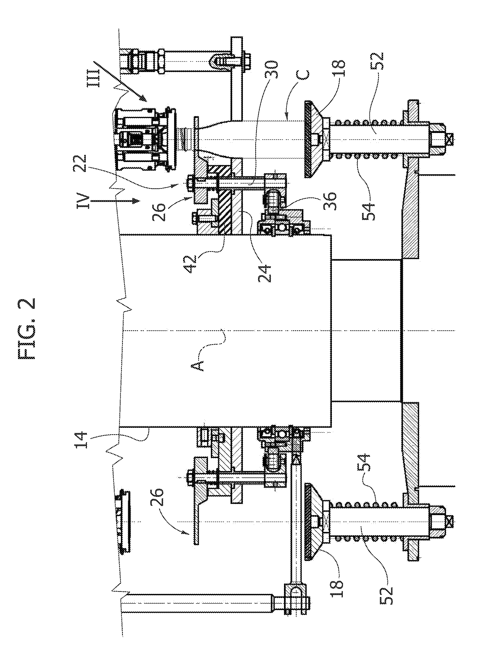
[0014]In the machine according to the present invention, the containers are withheld by grippers that grip the neck of the containers. The grippers are mobile in a vertical direction and, following upon application of the force of compression on the containers, come to rest on a support that receives the axial force applied on the cap. In this way, any flexural stress on the grippers and their pins is avoided.
[0015]Thanks to this arrangement it becomes possible to apply non-pre-threaded caps on containers with low resistance to compression, for example ones made of thin-walled aluminium.

Problems solved by technology

Machines of a known type cannot be used for applying non-pre-threaded caps on easily deformable containers, made for example of thin-walled aluminium.
The force of compression with which the heads for applying the caps press the caps on the containers would produce collapse of the containers.
In machines of this type, the axial force necessary for screwing the caps on the containers tends to subject the grippers and their pins to flexural stress.

Method used


Image

  • Machine for application of caps on containers such as bottles and the like
  • Machine for application of caps on containers such as bottles and the like
  • Machine for application of caps on containers such as bottles and the like

Examples


Embodiment Construction

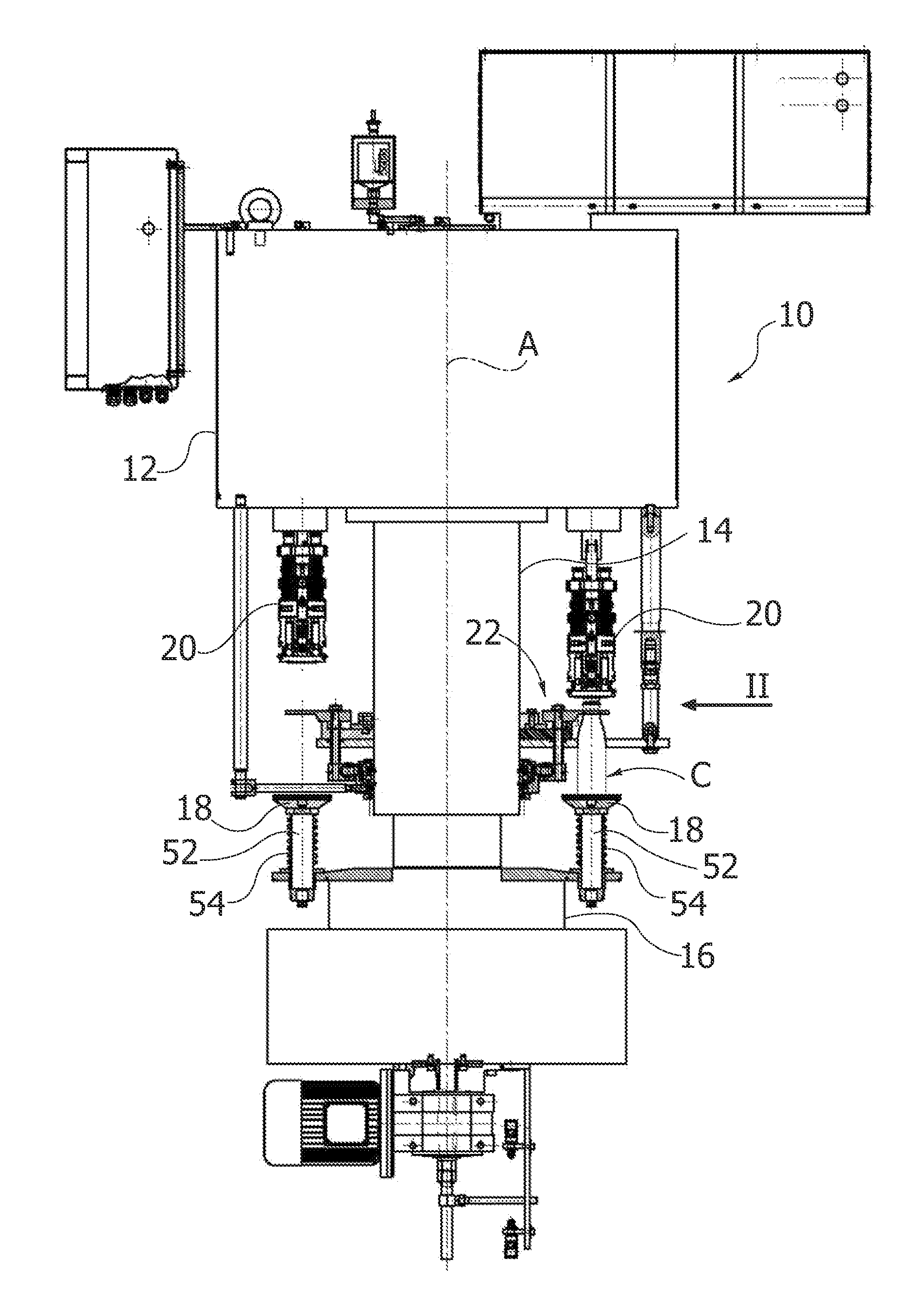
[0023]With reference to FIG. 1, designated by 10 is a machine for application of non-pre-threaded caps on containers C, such as bottles and the like. The machine 10 has a carousel structure, which can turn about a vertical axis A and comprises a top part 12, a central column 14, and a bottom base 16.

[0024]The bottom base 16 carries a plurality of cups 18, resting on which are respective containers C.

[0025]As may be seen in greater detail in FIG. 3, each container C has a neck N with a threaded end T. The neck N can be equipped with a further annular shoulder S situated underneath the threaded end T, already equipped with a first annular shoulder necessary for providing the rim at the bottom of the cap, which, after opening, remains fixed to the bottle.

[0026]The top part 12 of the machine 10 carries a plurality of rolling heads 20 (FIG. 1) designed to apply non-pre-threaded caps on the threaded end T of the containers C. In a known way, the heads 20 press the non-pre-threaded caps ax...


PUM


Abstract

A machine for application of caps on containers such as bottles and the like having a neck with a threaded top end, comprising at least one head for application of caps and at least one gripper designed to grip the neck of the containers during application of the caps. Said at least one gripper is mobile in a vertical direction between a raised position and a lowered position, wherein elastic means are present for pushing the gripper elastically towards the raised position and wherein in the lowered position the gripper rests on a resting plate so that at least part of the axial force applied by said head on the cap is discharged on said resting plate.

Description

CROSS-REFERENCE TO RELATED APPLICATIONS[0001]This application claims benefit of Italian patent application serial number TO2010A000817, filed Oct. 6, 2010, which is herein incorporated by reference.BACKGROUND OF THE INVENTION[0002]1. Field of the Invention[0003]The present invention relates to a machine for application of caps on containers such as bottles and the like having a neck with a threaded top end.[0004]The present invention can be used for application of non-pre-threaded metal caps or else for application of threaded caps made of plastic material.[0005]Machines for application of non-pre-threaded caps are equipped with one or more heads that apply the non-pre-threaded caps on the threaded end of the containers and deform plastically the side wall of the caps by means of an operation of rolling to form the thread of the cap in place.[0006]Machines for application of threaded caps are equipped with screwing heads that bestow upon the caps a helical movement with a pitch equa...

Claims


Application Information

Patent Timeline
Patent Type & Authority Applications(United States)
IPC IPC(8): B67B3/20
CPCB67B3/206B67B3/18
Inventor CIRIO, SERGIO
Owner AROL
Learn More