Rail system fuel tender

Inactive Publication Date: 2012-04-12
NICHINI PAUL +1
View PDF4 Cites 24 Cited by
  • Summary
  • Abstract
  • Description
  • Claims
  • Application Information

AI Technical Summary

Benefits of technology

[0017]FIG. 1 is a plan side view of the improved fuel tender of the present invention.
[0018]FIG. 2 is a plan side view of the improved fuel tender of the present invention coupled to a locomotive as part of a train.
[0019]FIG. 3 is a front plan view of the improved fuel te

Problems solved by technology

However, when the fuel carrying capability is onboard the locomotive there is a penalty paid in weight and capacity.
However, fuel tanks that are large enough to contain a sufficient quantity of pressurized fuel to practically fuel a locomotive are very costly.
Typically, unpowered fuel tenders negatively im

Method used


Image

  • Rail system fuel tender
  • Rail system fuel tender
  • Rail system fuel tender

Examples


Embodiment Construction

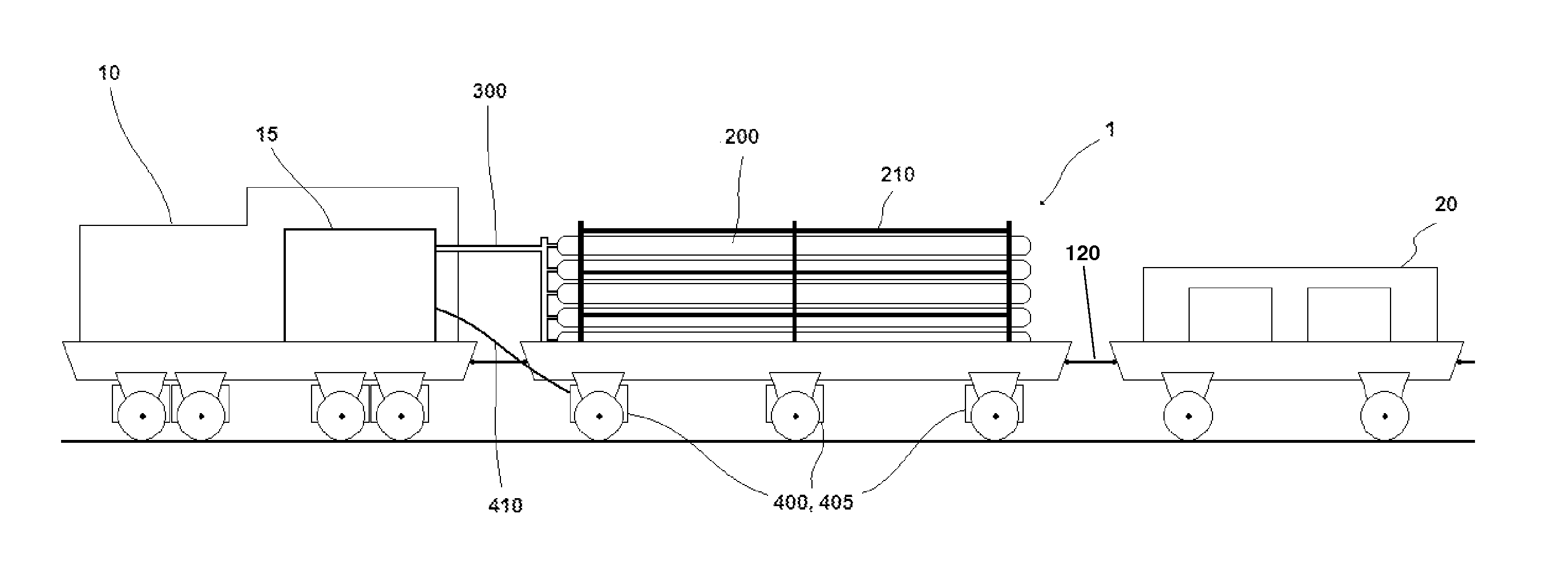
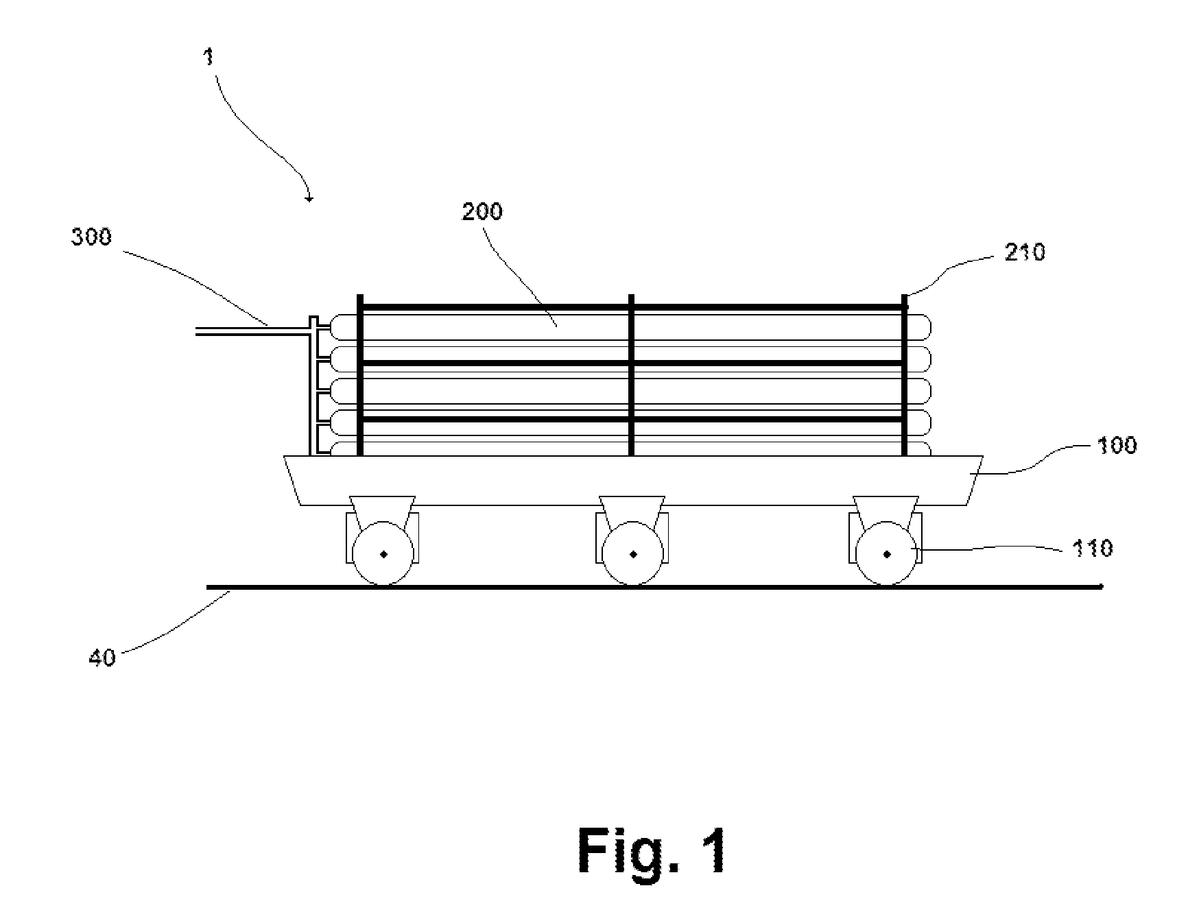
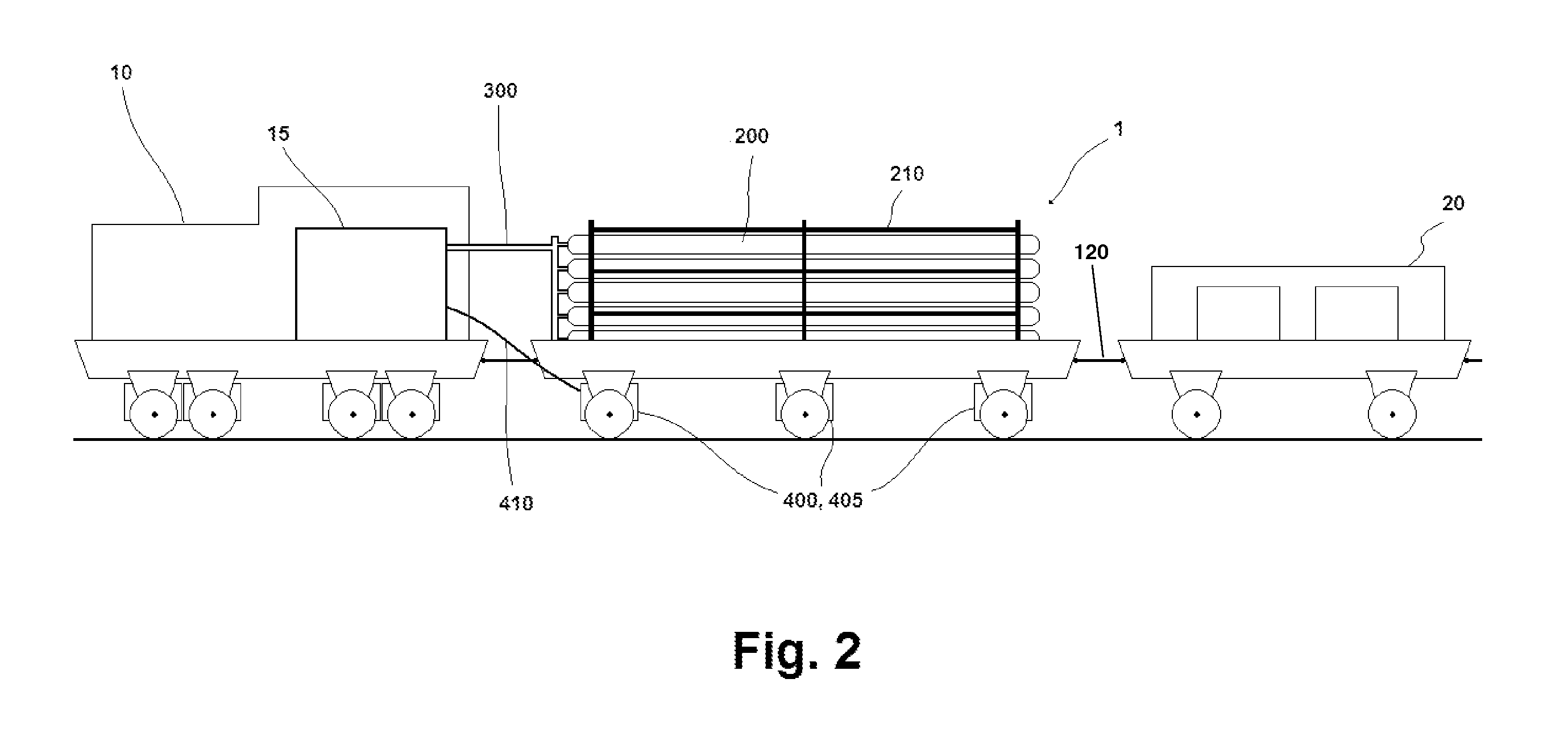
[0021]The present invention discloses an improved rail system fuel tender 1 for use with one or more railroad locomotives 10. See FIG. 1. The fuel tender 1 is a separate railroad vehicle from the one or more locomotives 10, and is intended to be used in connection with the one or more locomotives 10, see FIG. 2, the connection being either direct, e.g., the fuel tender 1 being coupled to a locomotive 10, or indirect, e.g., the fuel tender 1 being coupled to a railroad vehicle which is interposed between the fuel tender 1 and the locomotive 10. In the case of indirect coupling, the interposed railroad vehicle could be another locomotive 10 or another fuel tender 1. Thus, a single fuel tender 1 may be employed to fuel multiple locomotives 10, or multiple fuel tenders 1 may be employed to fuel multiple locomotives 10, as well as a single fuel tender 1 being employed to fuel a single locomotive 10.

[0022]The fuel tender 1 of the present invention comprises a chassis 100, and the chassis ...


PUM


Abstract

An improved rail system fuel tender for use with one or more railroad locomotives capable of transporting a plurality of fuel containers suitable for containing pressurized fuel and suitable for directly fueling the one or more locomotives. The improved fuel tender may be powered by the locomotives to increase tractive effort, and the fuel containers may be separately fillable and separately removable from the fuel tender.

Description

BACKGROUND OF THE INVENTION[0001]1. Technical Field[0002]The invention relates generally to the field of vehicles used on railroads. More specifically, the invention is directed to an improved fuel tender adapted to run on railroad rails as part of a train comprising at least one locomotive for which the improved fuel tender provides fuel.[0003]2. Description of Prior Art[0004]Railroad fuel tenders are well known in the art. From the earliest coal cars which were coupled to steam locomotive engines to the diesel tankers used more recently, separate vehicles have been employed to transport the fuel used by the locomotives powering trains. More recently there has been a trend towards integrating fuel carrying capability within the locomotive itself, much as an automobile has an integrated gas tank. One example is disclosed in U.S. Pat. No. 5,129,328 (Jul. 14, 1992, to Donnelly), whereby a gas turbine locomotive fueled by compressed natural gas carries gas storage tanks on the locomoti...

Claims


Application Information

Patent Timeline
IPC IPC(8): B61C17/02B61C3/00
CPCB61C17/02B61C5/00
Inventor NICHINI, PAULROWLAND, ROSS
Owner NICHINI PAUL
Why Eureka
Try Eureka