Heat sink and LED cooling system

a technology of led cooling system and heat sink, which is applied in the field of illumination sources, can solve the problems of device failure, subject to very limited wear and tear, etc., and achieve the effects of improving performance, prolonging the working life of leds, and improving cooling

Inactive Publication Date: 2012-04-12
COOL LUMENS
View PDF3 Cites 72 Cited by
  • Summary
  • Abstract
  • Description
  • Claims
  • Application Information

AI Technical Summary

Benefits of technology

[0012]An advantage of the present invention is it produces better cooling of LEDs and thus improves performance.
[0013]Another advantage of the present invention is it extends the working life of LEDs by providing better cooling.
[0014]A further advantage of the present invention is it makes LED lighting more dependable, and thus encourages their use for applications such as in medical devices, transportation devices, etc. where reliability is a very important factor.
[0015]And another advantage of the present invention is that by encouraging the use of more reliable LEDs, there are environmental benefits such as reducing carbon footprints of lighting devices.
[0016]A further advantage of the present invention is that it includes a cooling cavity between the back of the LED module and the interior channels. This dramatically increased the airflow past the back of the LED module. This cooling cavity is used in conjunction with the mounting plate for the angled version and also connects to the additional multiple side vents in the straight version.
[0017]A further advantage of the present invention is that it provides a heat sink housing which is configured as a finned concentric tube configuration.

Problems solved by technology

LEDs are solid state devices and if operated at low currents and at low temperatures, are subject to very limited wear and tear.
Over-heating of the LED is a major factor in device failure.
This is especially important to have a low failure rate when LEDs are used in automotive, medical, and military applications where the device must operate over a large range of temperatures, and failure could create serious problems.

Method used


Image

  • Heat sink and LED cooling system
  • Heat sink and LED cooling system
  • Heat sink and LED cooling system

Examples


Embodiment Construction

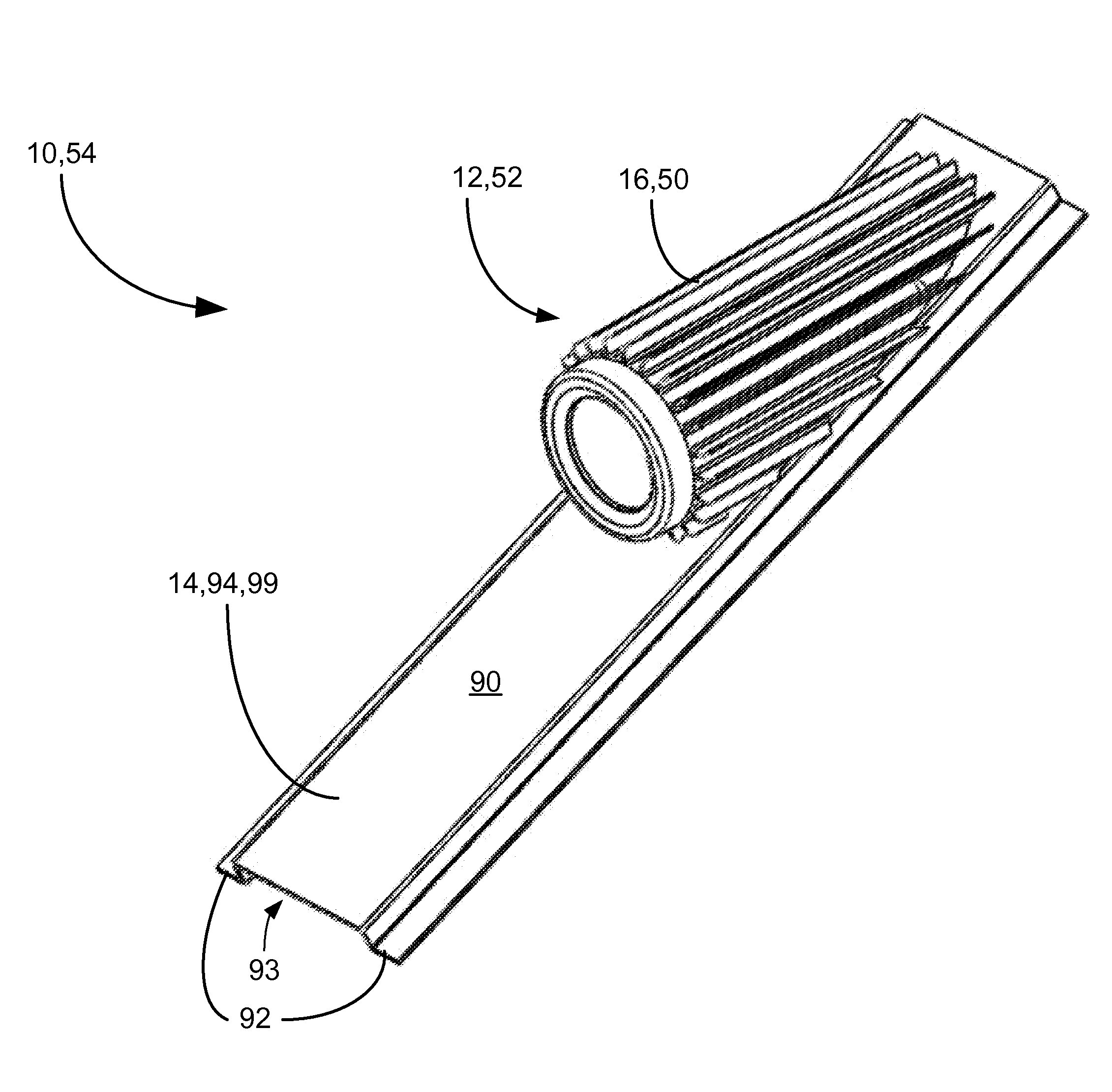
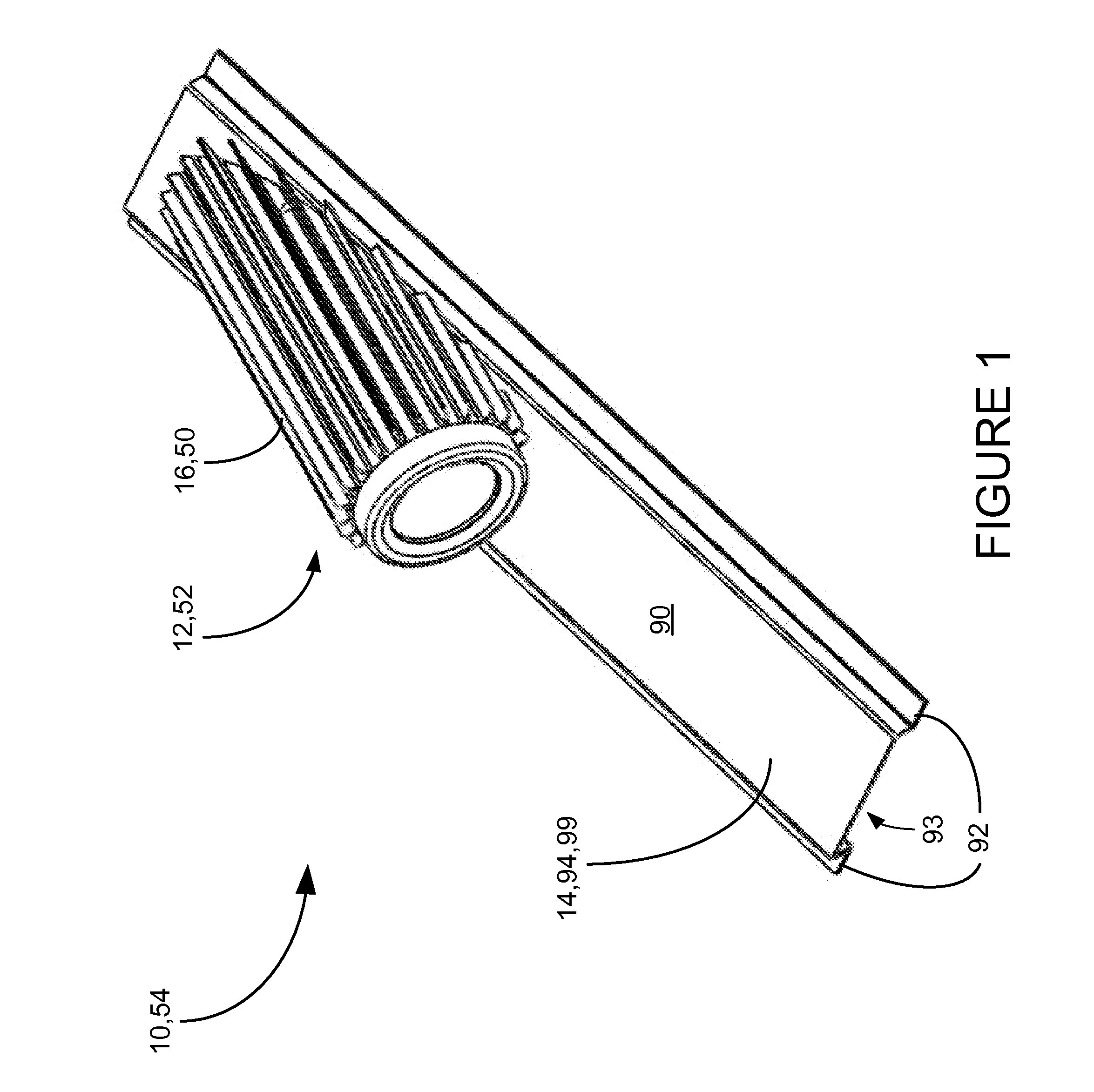
[0036]The present invention is a heat sink LED cooling system, which will be referred to by the reference number 10, and thus shall be referred to as LED cooling system 10. A first preferred embodiment of the LED cooling system 10 and its elements are illustrated in FIGS. 1-10.

[0037]FIG. 1 shows an isometric view of an assembled LED cooling system 10, which includes an LED heat sink assembly 12, and a frame 14, which in itself contributes to the heat transfer effectiveness, as will be discussed below.

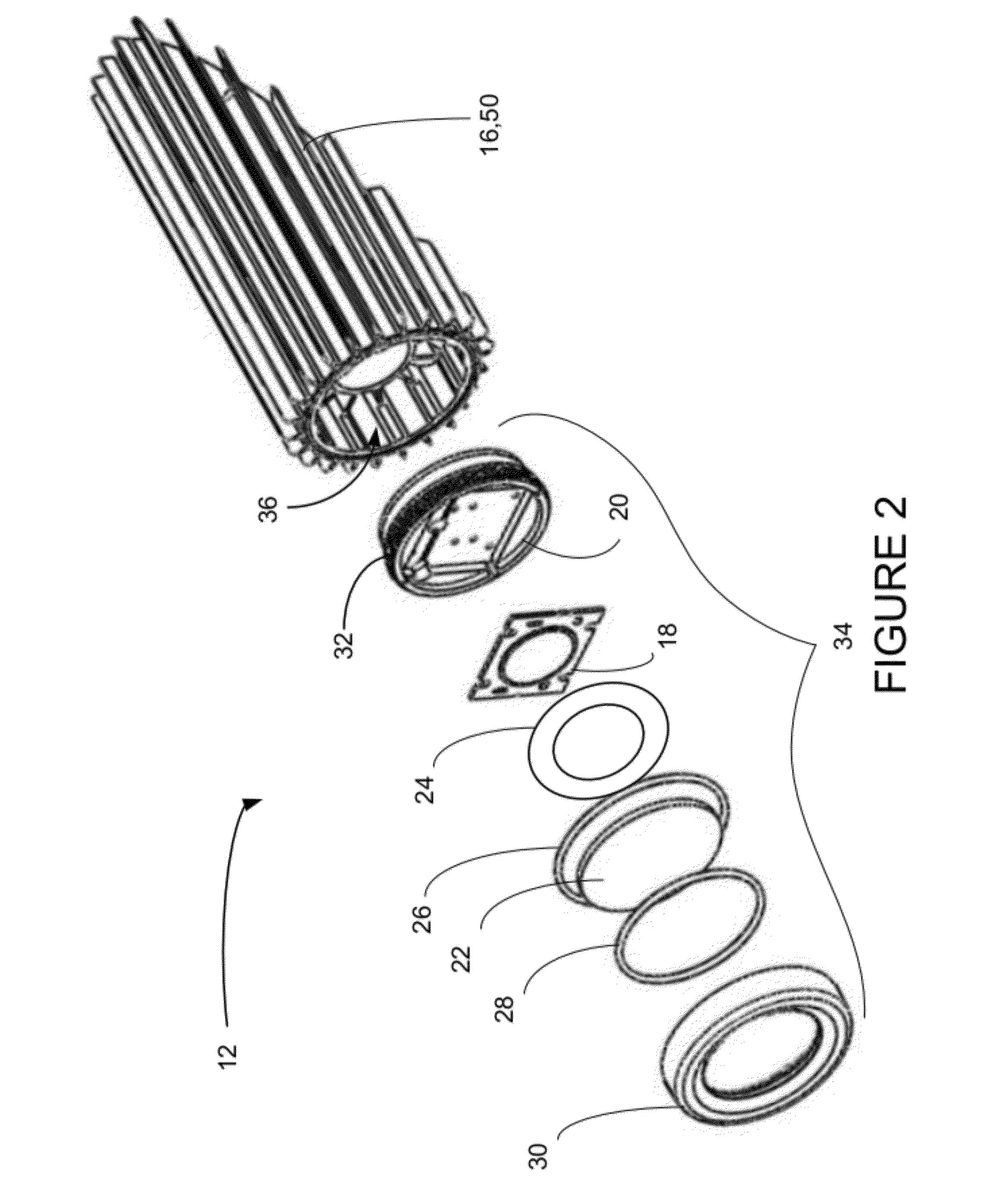
[0038]FIG. 2 shows an isometric exploded view of the LED heat sink assembly 12, which includes a heat sink housing 16, and an LED 18, which fits into an LED housing 20. A lens 22 is sandwiched between a shield 24, a first O-ring 26 and a second O-ring 28. A cap 30 attaches to the LED housing 20 by screw threads 32 (see FIG. 9). The assembly, which includes the LED housing 20, LED 18, lens 22, shield 24 and first and second O-rings 26, 28 shall be referred to as the LED module 34. This L...


PUM


Abstract

A heat sink for cooling LEDs, which includes a heat sink housing which is configured as a finned concentric tube configuration. Also, an LED heat sink assembly and an LED cooling system which include a heat sink housing which is configured as a finned concentric tube configuration. Also, a method for cooling LED modules.

Description

TECHNICAL FIELD[0001]The present invention relates generally to illumination sources and more particularly to heat sink devices for LED illumination sources.BACKGROUND ART[0002]An Light-Emitting Diode (LED) is a semiconductor light source, which have many practical applications due to their longer lifetime, faster switching, smaller physical size, greater durability and higher energy efficiency.[0003]When a light-emitting diode is forward biased, electrons (negative charges) recombine with holes (positive charges), which releases energy in the form of photons. The energy difference within the diode produces photons of different wavelengths, for different colors, which do not require color filters to produce. LEDs are solid state devices and if operated at low currents and at low temperatures, are subject to very limited wear and tear. Typical lifetimes are estimated to be 35,000 to 50,000 hours of useful life, compared to 10,000 to 15,000 hours for fluorescent tubes, and 1,000-2,000...

Claims


Application Information

Patent Timeline
Patent Type & Authority Applications(United States)
IPC IPC(8): F28F7/00F28F13/00
CPCF21V23/04F21Y2101/02F28F1/16F21V15/013F21V29/89F21V29/75F21V29/773F21V29/83F21V29/71F21Y2115/10
Inventor MCCLELLAN, THOMAS DAVID
Owner COOL LUMENS
Why Eureka
Try Eureka