Decorative Light System

a technology of decorative lights and string lights, applied in the field of light string lights, can solve the problems of material cost, and achieve the effects of reducing material cost, reducing bulk of wiring, and facilitating manufactur

Inactive Publication Date: 2012-04-12
SEGAN
View PDF8 Cites 31 Cited by
  • Summary
  • Abstract
  • Description
  • Claims
  • Application Information

AI Technical Summary

Benefits of technology

[0011]One objective of the present invention is to create a decorative (or holiday or similar) light string having individual lights that can be activated under completely independent control, thereby permitting any pattern of illumination. There are many practical constraints to achieving such a system, among them, cost of materials, ease and familiarity of manufacture, regulatory and safety compliance, and user-friendliness (including minimizing bulk of wiring). Example embodiments achieve this objective and others by distributing a plurality of microprocessor control circuits along a familiar light string with each disguised as a familiar replaceable bulb base and socket. Each microprocessor control circuit or remote unit contains program data to control adjacent lights under its immediate control and, instead of explicit instructions to each unit or light, requires only global control, time synchronization and user instructions. The few data bits required for such control are delivered through a subtle manipulation of the power waveform. The power supply may be a unique “stacking” of the low-voltage remote units that matches the voltage of the light string system to an AC plug supply and thus avoids the need for a transformer. A control unit coordinates the actions of the remote units and permits user control. However, a control unit is not necessarily required, and a light string according to an example embodiment may include remote units that initialize and synchronize upon receiving the AC waveform. The light string requires only two wires to power and control all of the remote units and allows various physical arrangements of the lights including “icicle” and straight-line sets.

Problems solved by technology

There are many practical constraints to achieving such a system, among them, cost of materials, ease and familiarity of manufacture, regulatory and safety compliance, and user-friendliness (including minimizing bulk of wiring).

Method used


Image

  • Decorative Light System
  • Decorative Light System
  • Decorative Light System

Examples


Embodiment Construction

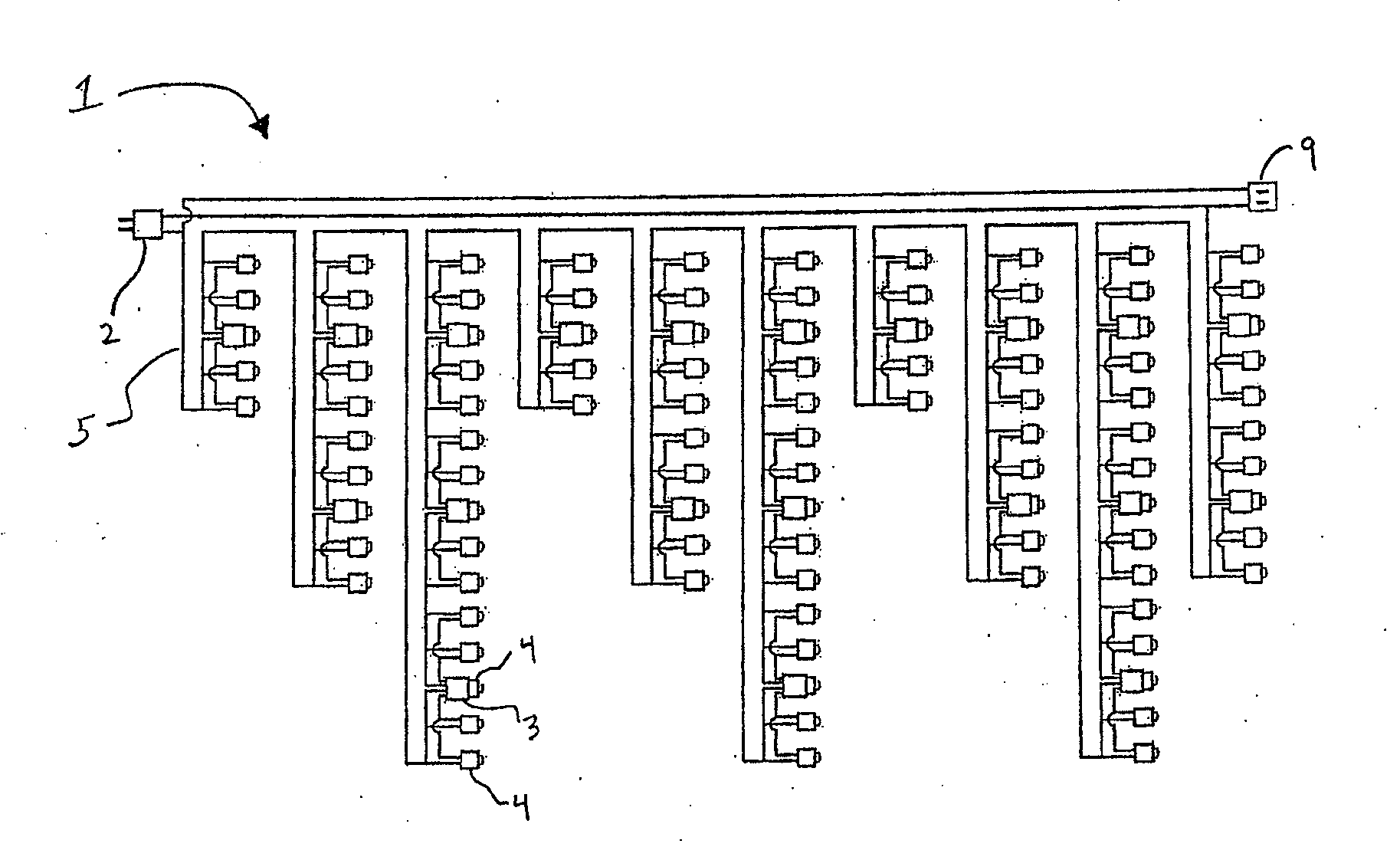
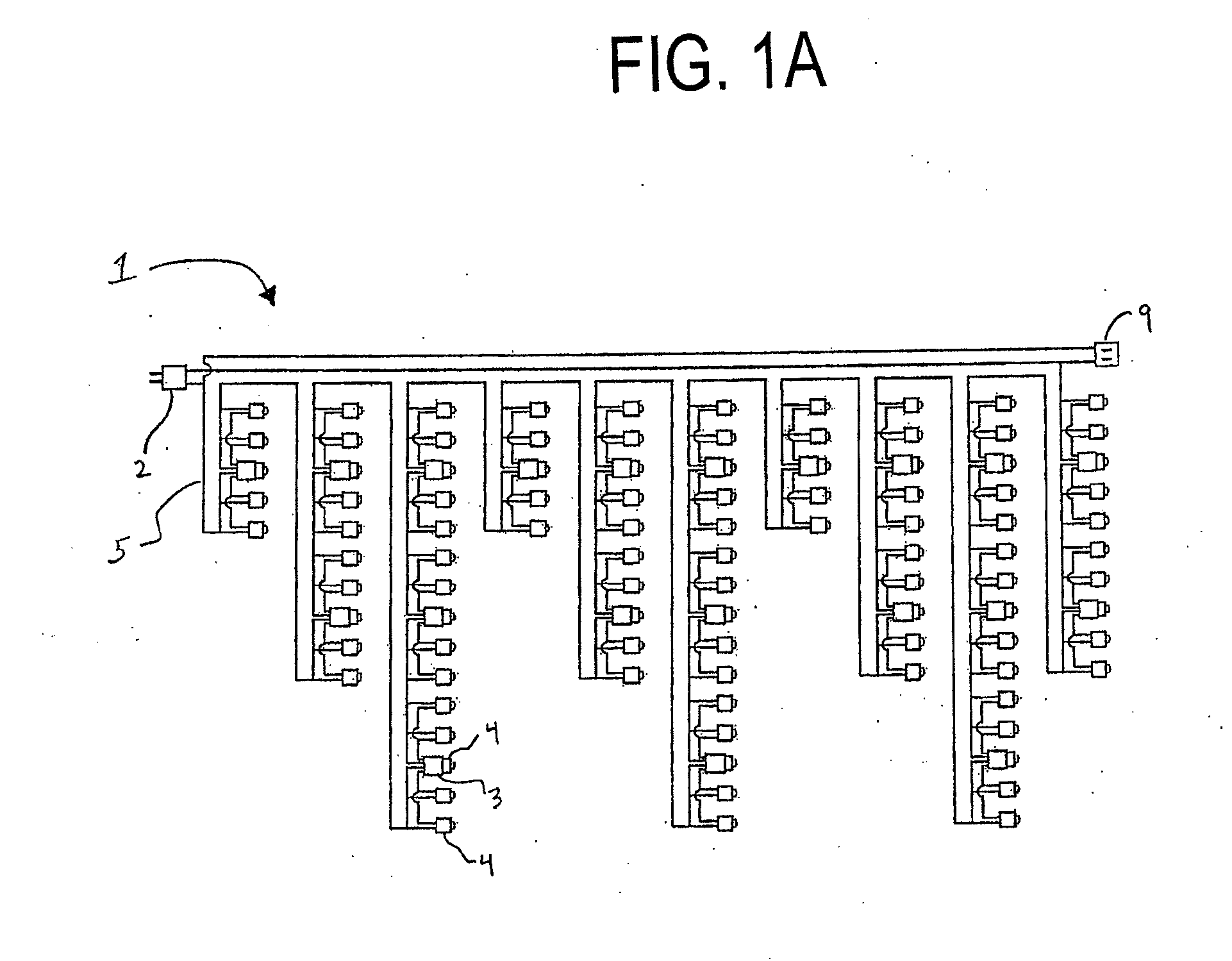
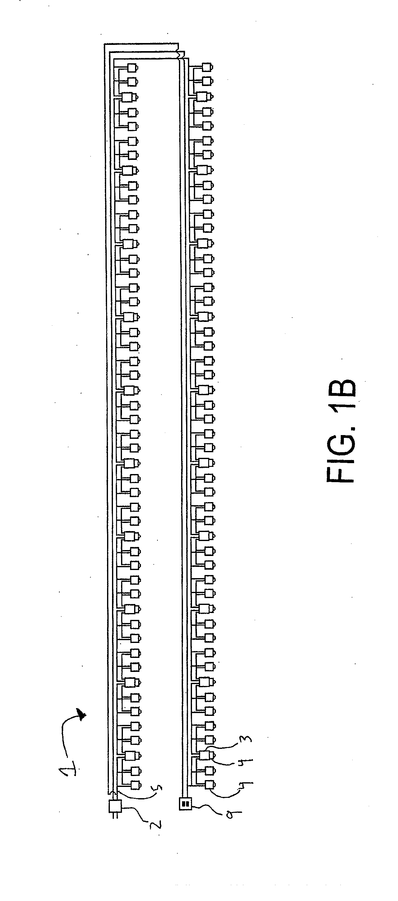
[0034]Example embodiments are directed to a decorative light string capable of independent control of each individual light. As shown in FIGS. 1A, 1B and 1C, a light string or system 1 according to an example embodiment includes a control unit 2, a plurality of remote units 3 and a plurality of lights 4. The lights 4 are preferably light emitting diodes (LEDs). Each remote unit 3 is configured to drive one or more “wing” lights 4 outboard of the remote unit 3 itself. The remote units 3 themselves physically include one or more of the lights 4. For example, the remote units 3 are integrated with one or more of the lights 4 and are physically nearly indistinguishable from the “wing” lights 4, thereby rendering the remote units 3 substantially camouflaged to a user so that the overall light string 1 appears nearly identical to a conventional standard light string. The light string 1 is preferably house-current AC-operated and employs preexisting parts from commonly available UL-approve...


PUM


Abstract

A light string includes a plurality of remote units and a control unit. Each of the plurality of remote units includes a microcontroller and is connected to a plurality of lights. Each microcontroller stores one or more programs for controlling the lights in the plurality of lights. The control unit is connected to the plurality of remote units by a power supply line. The control unit sends information via the power supply line to the plurality of remote units. The information indicates a program of the one or more programs to be executed by the microcontroller of each of the remote units to individually control the plurality of lights.

Description

RELATED APPLICATIONS[0001]This application claims priority from U.S. Provisional Patent Application Ser. No. 61 / 390,381 which was filed on Oct. 6, 2010.FIELD OF THE INVENTION[0002]The present invention relates to a light string and in particular to a light string having individual lights that can be activated under independent control.DESCRIPTION OF THE RELATED ART[0003]Originally created as a safer alternative to real candles on Christmas trees, electric Christmas lights have been manufactured and sold for nearly 100 years. Small wattage line-voltage (120V AC) bulbs, wired in parallel, were originally the only type offered. The 1970's brought so-called mini-lights, low-wattage, low-voltage bulbs wired in series. These lights generated much less heat and are much smaller and less expensive than line-voltage bulbs. Over the years, mini-lights have become extremely inexpensive, almost to the point of the cost of the commodities involved—copper, plastic, glass—as their manufacture and ...

Claims


Application Information

Patent Timeline
Patent Type & Authority Applications(United States)
IPC IPC(8): H05B37/02
CPCH05B33/0842H05B33/0803H05B45/31H05B45/325
Inventor SEGAN, MARC H.
Owner SEGAN
Why Eureka
Try Eureka