
Method for operating of a metal detection system and metal detection system

Active Publication Date: 2012-04-12
METTLER TOLEDO SAFELINE
View PDF0 Cites 19 Cited by
  • Summary
  • Abstract
  • Description
  • Claims
  • Application Information

AI Technical Summary

Benefits of technology

[0030]Applying filters to the selected transmitter frequencies, i.e. carrier frequencies, leads to a further significant improvement of the sensitivity of the metal detection system.

Problems solved by technology

However, a piece of magnetically and / or electrically conductive material, that passes through the balanced coil system, will disturb the magnetic field and will cause modifications of the electrical signal(s) induced in the receiver coils.
On the other hand, non-ferrous metals and particularly stainless steel are difficult to detect in wet products since their phase is similar to the product phase.
However, not every metal passing through a metal detection system is a contaminant, since it could be part of the product packaging.
Further, not all disturbances of the magnetic field of the receiver coils are caused by products and metal contaminants traveling through the “balanced coil system.” Vibrations of a conductive material near the balanced coil system may also cause signal changes in the receiver coils that need to be distinguished from signals caused by contaminated products.
Therefore, such products traveling through the balanced coil system also disturb the magnetic fields, thus causing a signal at the output of the receiver coils.
However, it has been found that the phase and the magnitude of the signals caused by the product and the metal contaminants depend on the applied transmitter frequency.
However, metal detection systems that operate at different frequencies typically have a lower sensitivity than systems that are tuned to a single frequency.
Hence, although signals of metal contaminants may be obtained with a desirable phase, the detection of these signals may still fail due to the low sensitivity of the metal detection system.
For transmitter frequencies above 300 kHz, low input impedance may unfavorably affect the sensitivity of metal contaminant signals.

Method used


Image

  • Method for operating of a metal detection system and metal detection system
  • Method for operating of a metal detection system and metal detection system
  • Method for operating of a metal detection system and metal detection system

Examples


Embodiment Construction

)

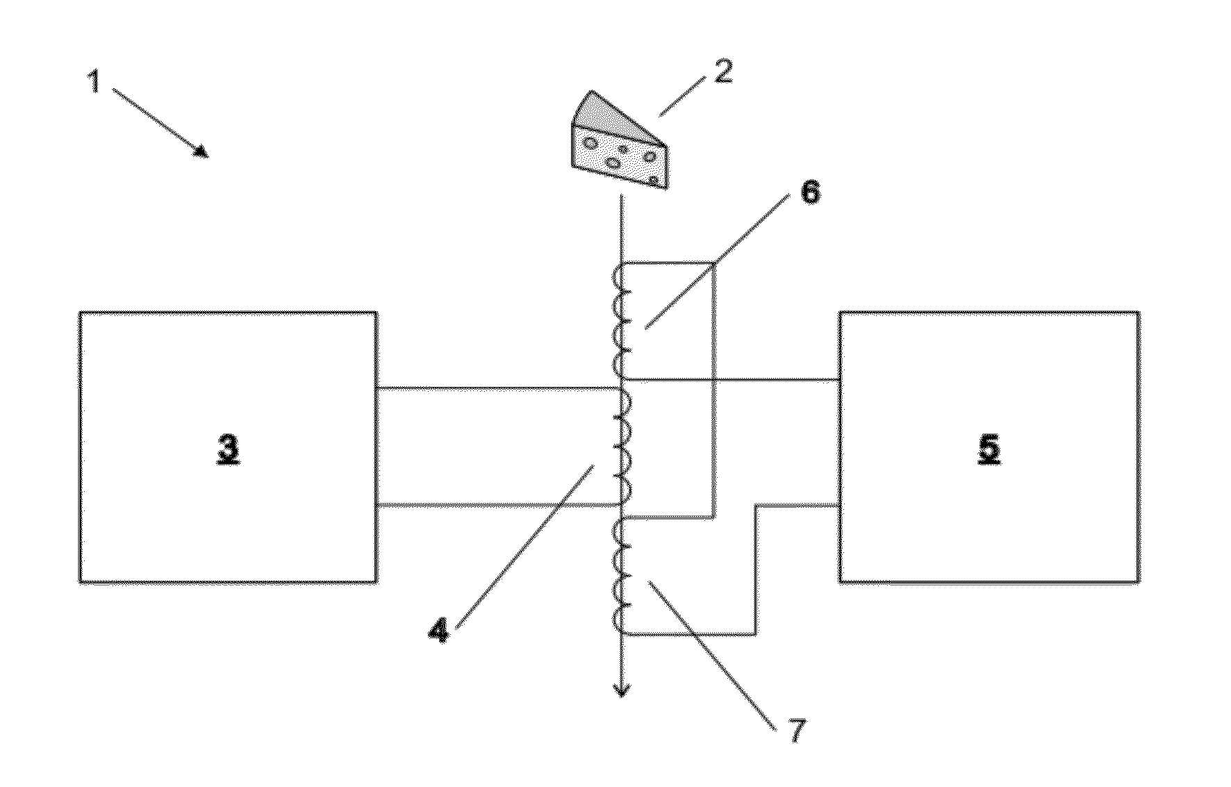
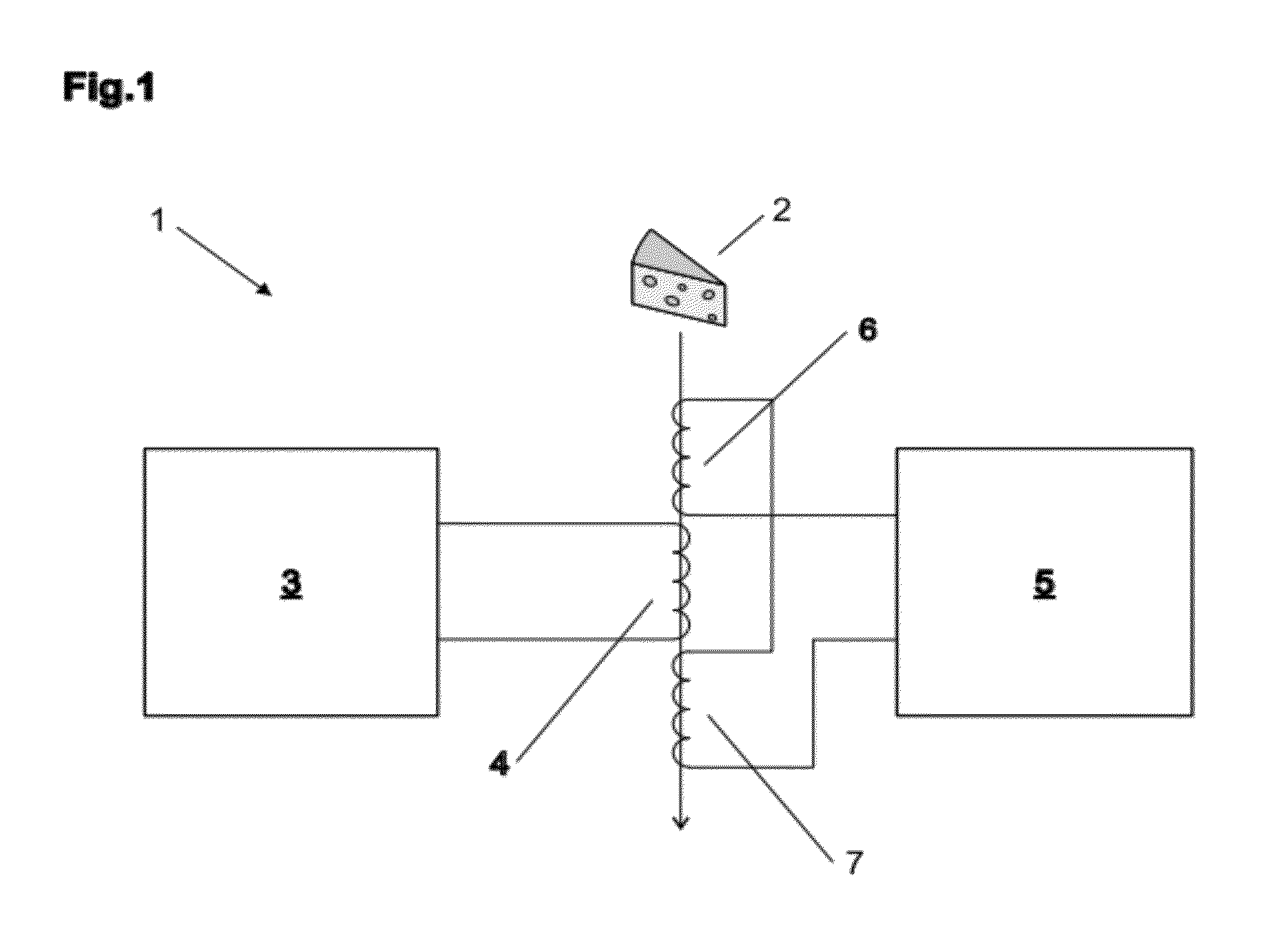
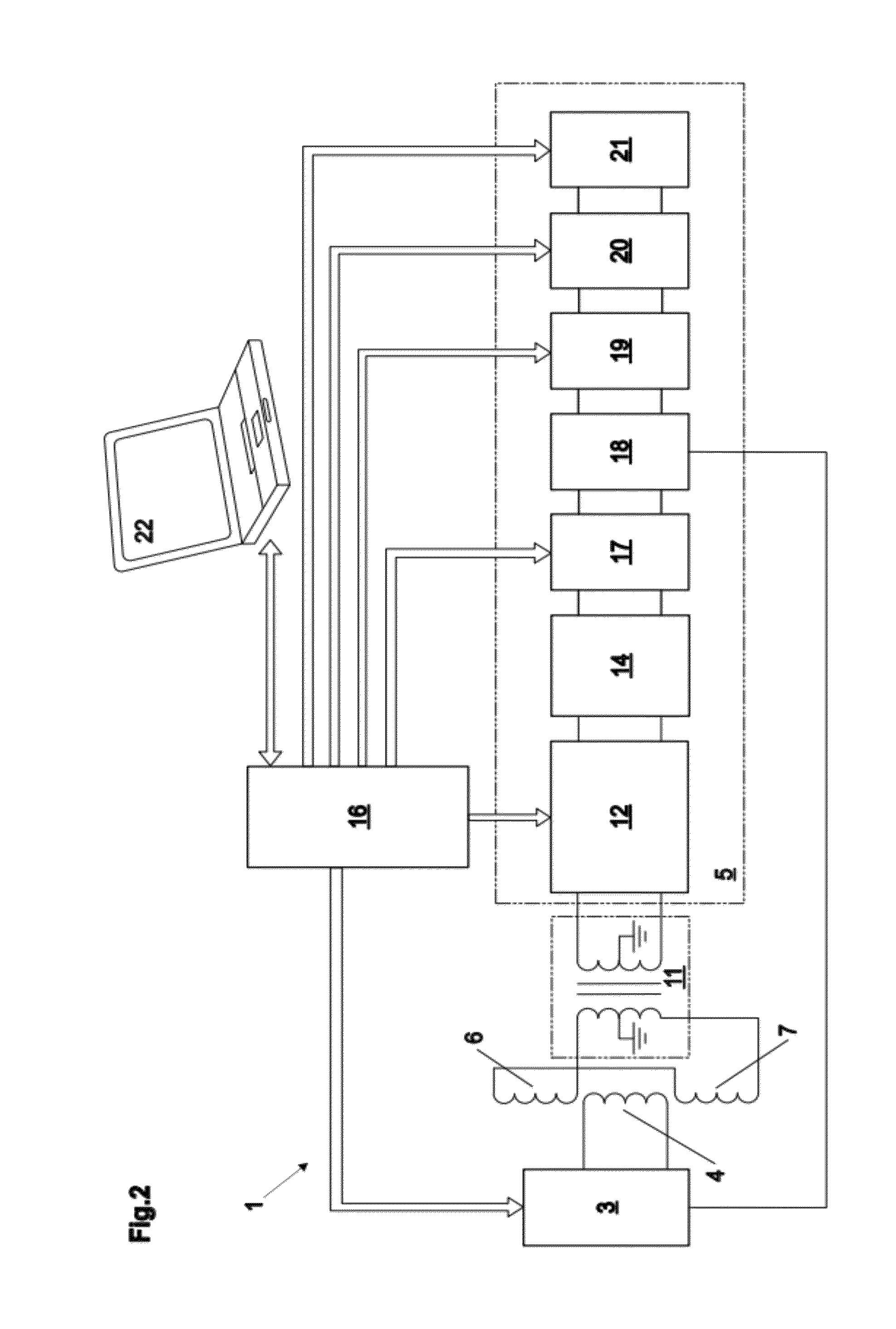
[0049]FIG. 1 shows a block diagram of an embodiment of a metal detection system 1 that essentially comprises a transmitter unit 3, a balanced coil system 4, 6, 7, a receiver unit 5, and a signal processing unit.

[0050]This example of the balanced coil system comprises a transmitter coil 4 and two receiver coils 6, 7 wound on a non-metallic frame, each exactly parallel with the others. The center coil is the transmitter coil 4, which is placed exactly equidistant from the identical receiver coils 6, 7 in this embodiment. The transmitter unit 3 generates a high frequency electric current that circulates through the transmitter coil 4. The current flowing through the transmitter coil 4 generates a magnetic field, which induces identical currents in the neighboring receiver coils 6, 7. The receiver coils 6, 7 are connected in opposition, i.e., both windings are wound in inverse directions, so that the currents induced in the receiver coils 6, 7 flow in opposite directions, and thus canc...


PUM


Abstract

A method for operating of a metal detection system may comprise a balanced coil system with a transmitter coil that is connected to a transmitter unit, which generates transmitter signals having a transmitter frequency that is selected from a group of at least two transmitter frequencies, and with a first and a second receiver coil that provide output signals to a signal input of at least one amplifier unit included in a receiver unit, wherein the output signals compensate each other so that the system is in balance. A system adapted to operate according to an exemplary method is also provided. In an exemplary embodiment, a control unit generates a control signal according to the transmitter frequency of the transmitter unit and that is provided to the control input of at least one controllable impedance unit, which is coupled to the signal input of the at least one amplifier unit, wherein the control signal is adapted to control the impedance value of the at least one controllable impedance unit in such a way that the impedance value is increased or lowered when the transmitter frequency is increased or lowered.

Description

[0001]This application claims priority under 35 U.S.C. §119 to European Patent Application No. 10186893.3, filed on Oct. 7, 2010, which is hereby incorporated by reference in its entirety.BACKGROUND AND SUMMARY OF THE INVENTION[0002]Exemplary embodiments of the present invention relate generally to a method for operating a metal detection system and to a metal detection system operating according to this method.[0003]In the industry where machinery is involved in the production of goods, there is always a possibility that a piece of metal, such as a screw or a bolt, does break away from the machinery, and finally ends up in the processed product. Therefore metal detection systems are used at various stages of a production process to detect products that are contaminated by metal. Metal detection systems are also often used for inspecting finished product, in order to ensure consumers' safety and quality standards.[0004]Most modern metal detection systems utilize a search head compri...

Claims


Application Information

Patent Timeline
IPC IPC(8): G01V3/08
CPCG01V3/107
Inventor MCADAM, STEPHEN
Owner METTLER TOLEDO SAFELINE
Learn More