
Method and device for determining processed image data about a surround field of a vehicle

a technology for processing image data and vehicle surround, which is applied in the direction of vehicle components, geometric image transformation, instruments, etc., to achieve the effect of eliminating distortion

Active Publication Date: 2012-04-12
ROBERT BOSCH GMBH
View PDF6 Cites 48 Cited by
  • Summary
  • Abstract
  • Description
  • Claims
  • Application Information

AI Technical Summary

Benefits of technology

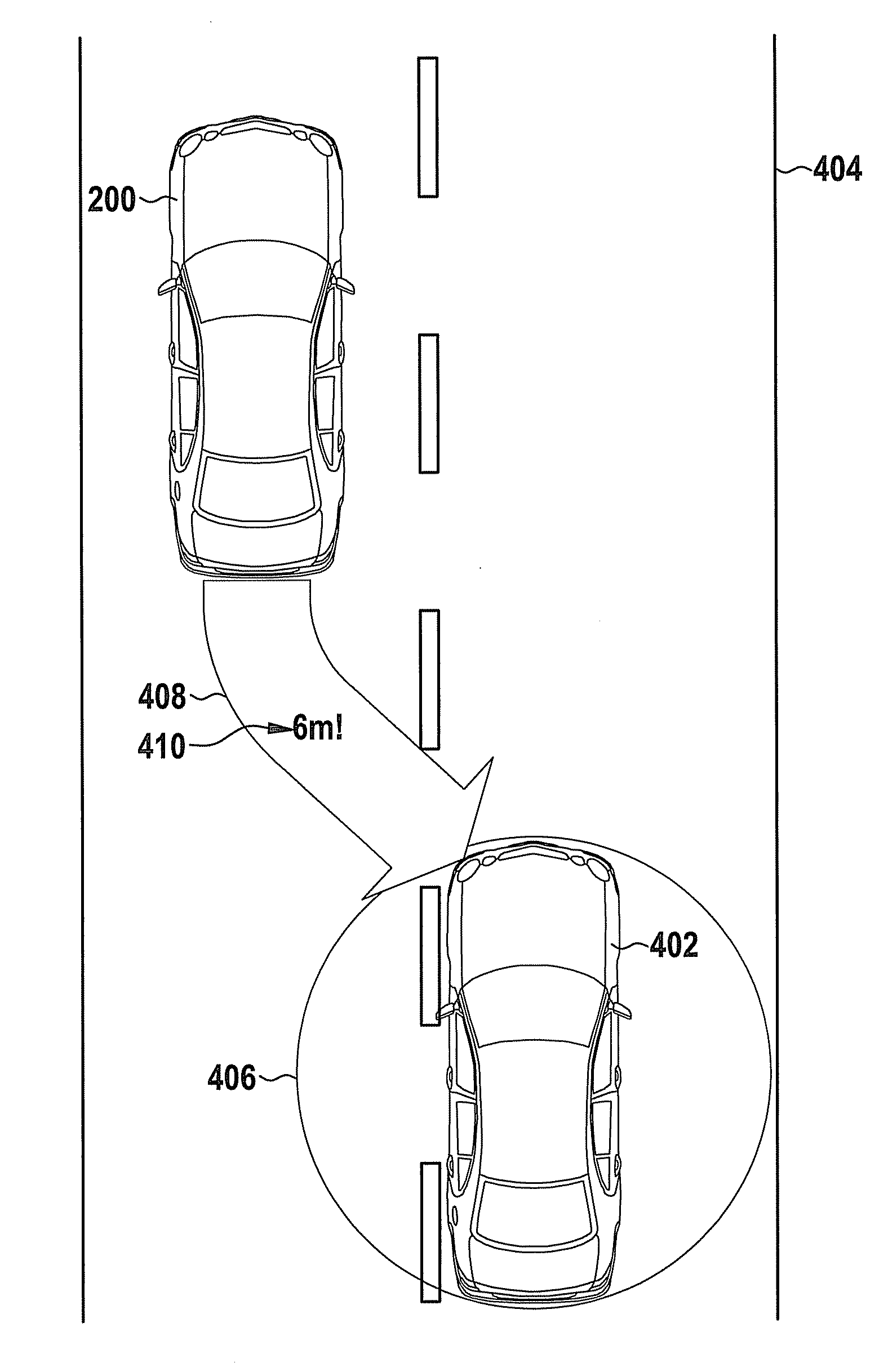
[0006]The essence of the present invention is a synthetic, abstracted, intuitive visualization of the vehicle surroundings, in which the objects relevant to the driving task, such as obstacles relevant to a collision, curbs or road markings, as well as information such as no-parking zones, parking fees or distance grids, are represented in highlighted form in the vehicle display, preferably, in the display of a head unit. The approach according to the present invention allows additional information relevant to the driver to be additionally made visible, i.e., permits a new type of display. This further information is partly generated by image processing algorithms and partly obtained by linking to a digital map, as is used in navigation, and partly obtained via the Internet. In an advantageous manner, the approach according to the present invention may prevent the relative relationship to the real world from being lost by elimination of distortion and changing the perspective. In addition, ranges and distances may be displayed for the driver in an intuitively correct manner. This is rendered possible by metrologically assisting the driver in the form of information regarding distances to possible obstacles.
[0007]In addition, the driver may be given assistance in finding parking spaces by intuitively inserting no-parking zones in the aerial perspective view. The elimination of distortion from objects, which are detected by the cameras in an incomplete and, occasionally, highly misleading manner, results in images that do not correspond to human visual perception. The present invention may eliminate this shortcoming by making synthetic objects visible, which produces a display for the driver that is considerably more understandable.
[0008]The insertion of the additional information, i.e., the type of display, may increase the immediate benefit to the driver, by preventing accidents or violations of traffic rules. In addition, the type of display of the vehicle surround field according to the present invention increases the emotional value of the “Surround View System.”
[0011]The method may include a step of adapting an orientation and / or a scaling of the symbol to the classified object in the processed image data. Symbols, which are used for representing the information in the image data, may strengthen an impression of the realism of the processed data via true-to-scale implementation and arrangement. In this manner, the driver may link the display more easily to the perceived reality.
[0012]In the processing step, the position-specific image may be processed so as to include a portrayal of distance, the portrayal of distance being formed in order to represent, in the processed image data, a distance between a classified object and the vehicle and / or distance lines in an open space navigable for the vehicle. The portrayal of distance may be implemented in the form of a grid as a distance grid. A representation using lines of equal distance from the vehicle, or a representation as text, is also possible. Making the distance information visible may allow a direct relationship between the processed image data and the surroundings of the vehicle to be produced for the driver.

Problems solved by technology

The elimination of distortion from objects, which are detected by the cameras in an incomplete and, occasionally, highly misleading manner, results in images that do not correspond to human visual perception.

Method used


Image

  • Method and device for determining processed image data about a surround field of a vehicle
  • Method and device for determining processed image data about a surround field of a vehicle
  • Method and device for determining processed image data about a surround field of a vehicle

Examples


Embodiment Construction

[0026]In the subsequent description of exemplary embodiments of the present invention, the same or similar reference numerals are used for the elements that are shown in the various figures and function similarly, while a repeated description of these elements is omitted.

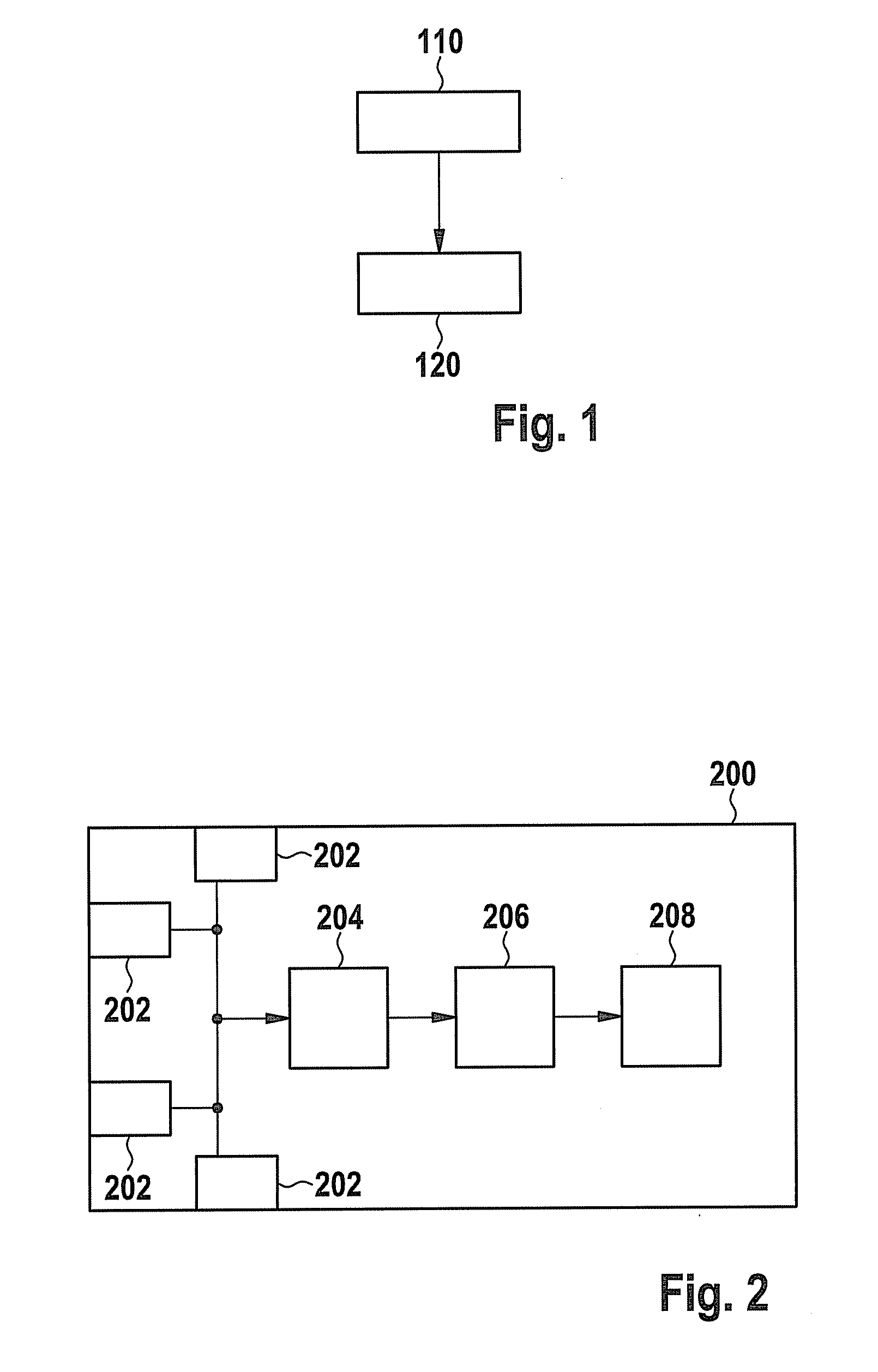
[0027]FIG. 1 shows a block diagram of a method for determining processed image data about a surround field of a vehicle, according to an exemplary embodiment of the present invention. In a step 110, a map information item is combined with a position of the vehicle, an orientation of the vehicle and an image of the surround field. The combining produces a position-specific image of the surround field. In a step 120, the position-specific image is processed to include at least one symbol, in order to obtain the processed image data. In this context, the symbol is assigned to a classified object that is encompassed by the position-specific image.

[0028]The map information, information about the position and the image of...


PUM


Abstract

A method for determining processed image data about a surround field of a vehicle includes a step of combining a map information item with a position and an orientation of the vehicle and with an image of the surround field acquired by a surround-field monitoring device of the vehicle, in order to obtain a position-specific image of the surround field. In addition, the method includes a step of processing the position-specific image so as to include at least one symbol that is assigned to a classified object in the position-specific image, in order to determine the processed image data.

Description

BACKGROUND OF THE INVENTION[0001]1. Field of the Invention[0002]The present invention relates to a method and a device for determining processed image data about a surround field of a vehicle, as well as to a corresponding computer program product.[0003]2. Description of Related Art[0004]Published German patent application document DE 10 2009 005 505 Al describes a method for generating an image of the surroundings of a motor vehicle with respect to a virtual camera position, from the images of at least one camera situated at the motor vehicle. The camera images are converted to the virtual camera position and corrected by including further data regarding the surround field of the motor vehicle.[0005]Known systems for an aerial perspective view of a vehicle surround field are limited to elimination of distortion, combining individual images, and to depicting the aerial perspective view in a simple manner.BRIEF SUMMARY OF THE INVENTION[0006]The essence of the present invention is a s...

Claims


Application Information

Patent Timeline
Patent Type & Authority Applications(United States)
IPC IPC(8): G06K9/00
CPCB60R1/00B60R2300/105G06T3/00B60R2300/307B60R2300/607B60R2300/305B60R1/27
Inventor FOCKE, THOMASVON ZITZEWITZ, HENNINGENGELBERG, THOMAS
Owner ROBERT BOSCH GMBH
Learn More