Apparatus and method for inspecting surface state

a surface state and apparatus technology, applied in the field of surface state inspection techniques, can solve the problems of difficult to accurately distinguish between inspection images and detected defects, difficult to detect flaws b, and difficult to discriminate between flaws and stainings, etc., to achieve accurate discrimination from each other, simple processing, and discrimination of irregularity and depth of flaws

Active Publication Date: 2012-04-12
ORMON CORP
View PDF6 Cites 7 Cited by
  • Summary
  • Abstract
  • Description
  • Claims
  • Application Information

AI Technical Summary

Benefits of technology

[0027]According to one or more embodiments of the present invention, the flaw and the stain can be accurately discriminated from each other from one or the plura

Problems solved by technology

Therefore, although the flaw and the stain are easily detected without distinguishing between the flaw and the stain, it is difficult to discriminate whether the detected defect is the flaw or the stain.
However, as shown in FIG. 17B, when the irradiation direction of the lighting is substantially identical to the flaw direction, the flaw does not clearly become the dark portion on the inspection image, it is difficult to detect a flaw B in the inspection image using lighting A, and it is difficult to detect a flaw A in the inspection image using lighting B. Therefore, when the flaw direction is indefinite or unknown, it is necessary that th

Method used


Image

  • Apparatus and method for inspecting surface state
  • Apparatus and method for inspecting surface state
  • Apparatus and method for inspecting surface state

Examples


first embodiment

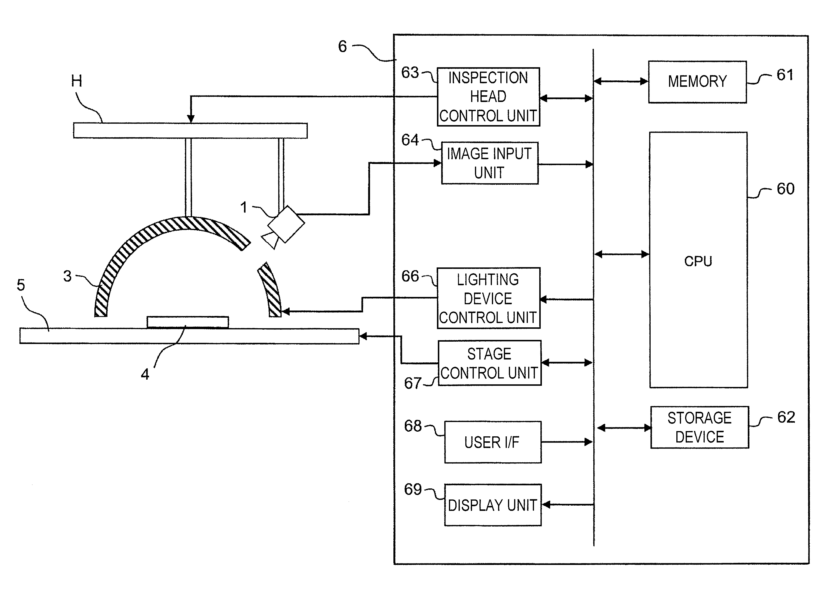
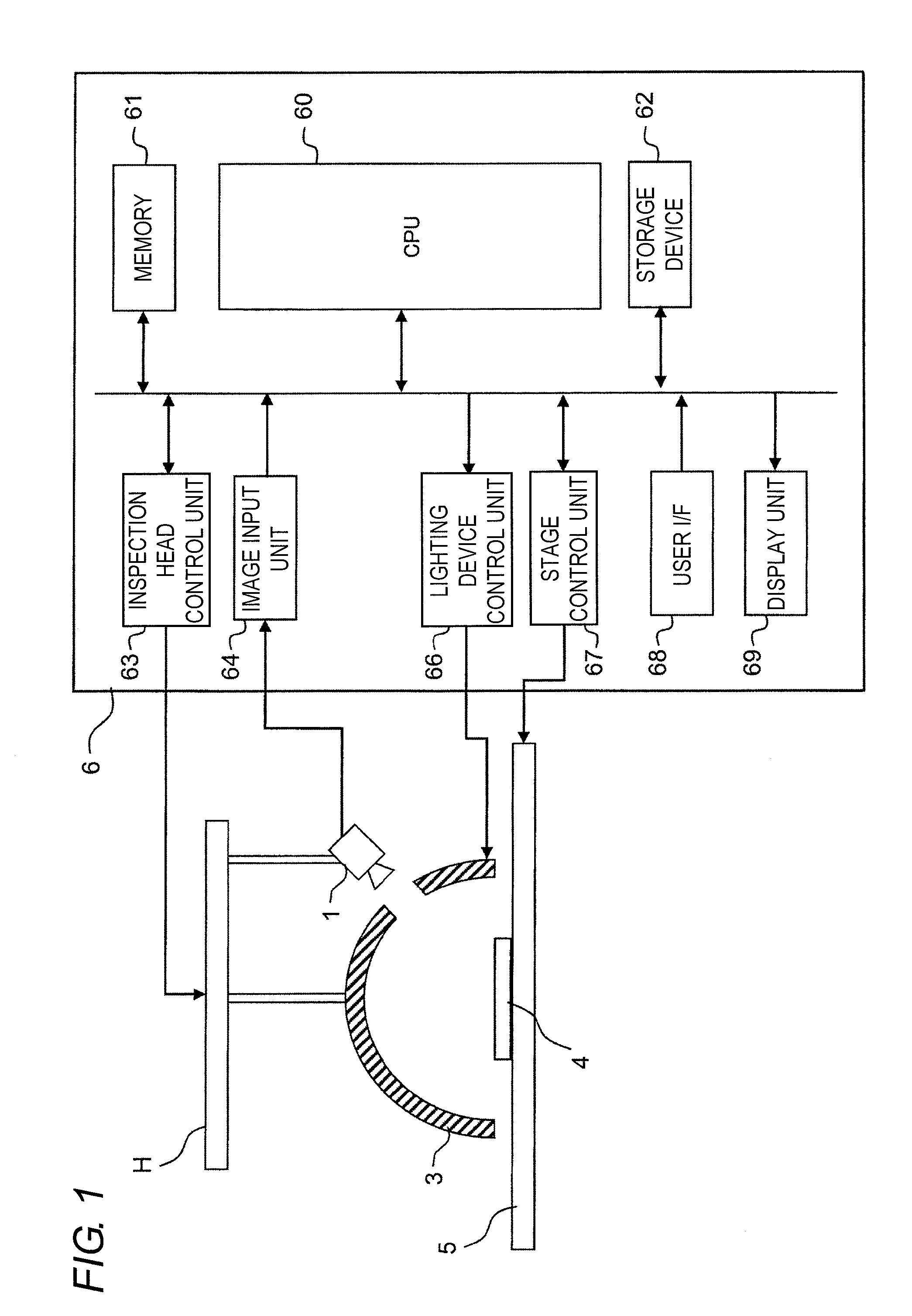
[0046]An entire configuration of the inspection apparatus will be described with reference to FIG. 1. FIG. 1 is a view schematically showing a hardware configuration of the inspection apparatus.

[0047]The inspection apparatus roughly includes a stage 5, an inspection head H, and an information processing device 6. A lighting device 3 and a camera (image sensor) 1 are attached to the inspection head H. The lighting device 3 irradiates an inspection target 4 placed on the stage 5 with measuring light. The camera 1 takes an image of the inspection target 4 from obliquely above. The information processing device 6 includes a CPU (Central Processing Unit) 60, a memory 61, a storage device 62, an inspection head control unit 63, an image input unit 64, a lighting device control unit 66, a stage control unit 67, a user I / F 68, and a display unit 69. The inspection head control unit 63 has a function of controlling movement of the inspection head H in a Z-direction (a direction perpendicular...

second embodiment

[0092]Occasionally a colored stain adheres to the surface depending on the inspection target. The colored stain means one, in which not the mirror reflection but the diffuse reflection becomes dominant in the portion to which the stain adheres and the color of the stain is observed as the reflected light. For the colored stain, because the color of the stain emerges on the inspection image irrespective of the color of the light incident from the regular reflection direction, the discrimination whether the colored stain is the stain or the flaw is hardly made only by checking the difference in hue between the colored stain and the surroundings (portion in which the stain does not exist). FIG. 15A shows an example. The colored stain exists in the surface of the inspection target 4, and the hue of the colored stain is accidentally matched with that of the color of the reflected light in the flaw portion. Therefore, the colored stain and the flaw cannot be distinguished from each other ...


PUM


Abstract

A surface state inspection apparatus has a lighting device that irradiates an inspection target placed on a stage with light, an imaging device that images the inspection target, and a detection device that detects a surface defect of the inspection target by analyzing a first inspection image obtained by the imaging device. The lighting device is a surface light source that includes a light emission region having a predetermined size and, in the lighting device, portions of light emitted from positions in the light emission region differ from each other in a spectral distribution. The detection device detects a portion in which a hue is different from that of its surrounding portion in the inspection target surface as a flaw. The detection device detects a portion in which the hue is substantially equal to that of its surrounding portion while brightness is different from that of its surrounding portion as a stain.

Description

BACKGROUND OF THE INVENTION[0001]1. Technical Field[0002]The present invention relates to a technique of inspecting a surface state of an object.[0003]2. Related Art[0004]There is well known a technique of inspecting the surface state of the object by analyzing an image obtained with a camera or an image sensor. This is generally called appearance inspection. For example, the appearance inspection is utilized to detect surface defects of magnetic and optical disks, a copper-clad laminate, a silicon wafer, a steel plate and a steel sphere, and a molded product.[0005]For example, in a technique proposed in Japanese Unexamined Patent Publication No. 5-322543, a flat-plate surface light source irradiates an object surface with inspection light having a lightness gradient, and a portion whose lightness gradient is different from that of its surrounding portion in an image is determined as a defect. In a technique proposed in Japanese Unexamined Patent Publication No. 2009-97977, four pie...

Claims


Application Information

Patent Timeline
IPC IPC(8): G06K9/00
CPCG06T7/0004G06T2207/30148G06T2207/30136
Inventor MORI, YASUMOTOMITSUMOTO, DAISUKEOHNISHI, YASUHIRONAYAR, SHREE
Owner ORMON CORP
Why Eureka
Try Eureka