Fiber delivery apparatus and system having a creel and fiber placement head with polar axis of rotation

Active Publication Date: 2012-04-19
INGERSOLL MACHINE TOOLS
View PDF4 Cites 8 Cited by
  • Summary
  • Abstract
  • Description
  • Claims
  • Application Information

AI Technical Summary

Benefits of technology

[0013]Embodiments of the present invention relate to fiber placement systems for forming fiber composite components. More particularly, embodiments of the present in

Problems solved by technology

Several problems exist in the current state of the art relating to fiber placement manufacturing apparatuses and methods.
A further issue in current fiber placement manufacturing apparatuses and methods is the way that tows are prepared for lay-up within the fiber placement device prior to being used by the fiber placement head.
Unfortunately, if there are changes in the path along which the fiber tows are dispensed from the spool to the fiber placement head, when the path becomes shorte

Method used


Image

  • Fiber delivery apparatus and system having a creel and fiber placement head with polar axis of rotation
  • Fiber delivery apparatus and system having a creel and fiber placement head with polar axis of rotation
  • Fiber delivery apparatus and system having a creel and fiber placement head with polar axis of rotation

Examples


Example

[0044]While the invention will be described in connection with certain preferred embodiments, there is no intent to limit it to those embodiments. On the contrary, the intent is to cover all alternatives, modifications and equivalents as included within the spirit and scope of the invention as defined by the appended claims.

DETAILED DESCRIPTION OF THE INVENTION

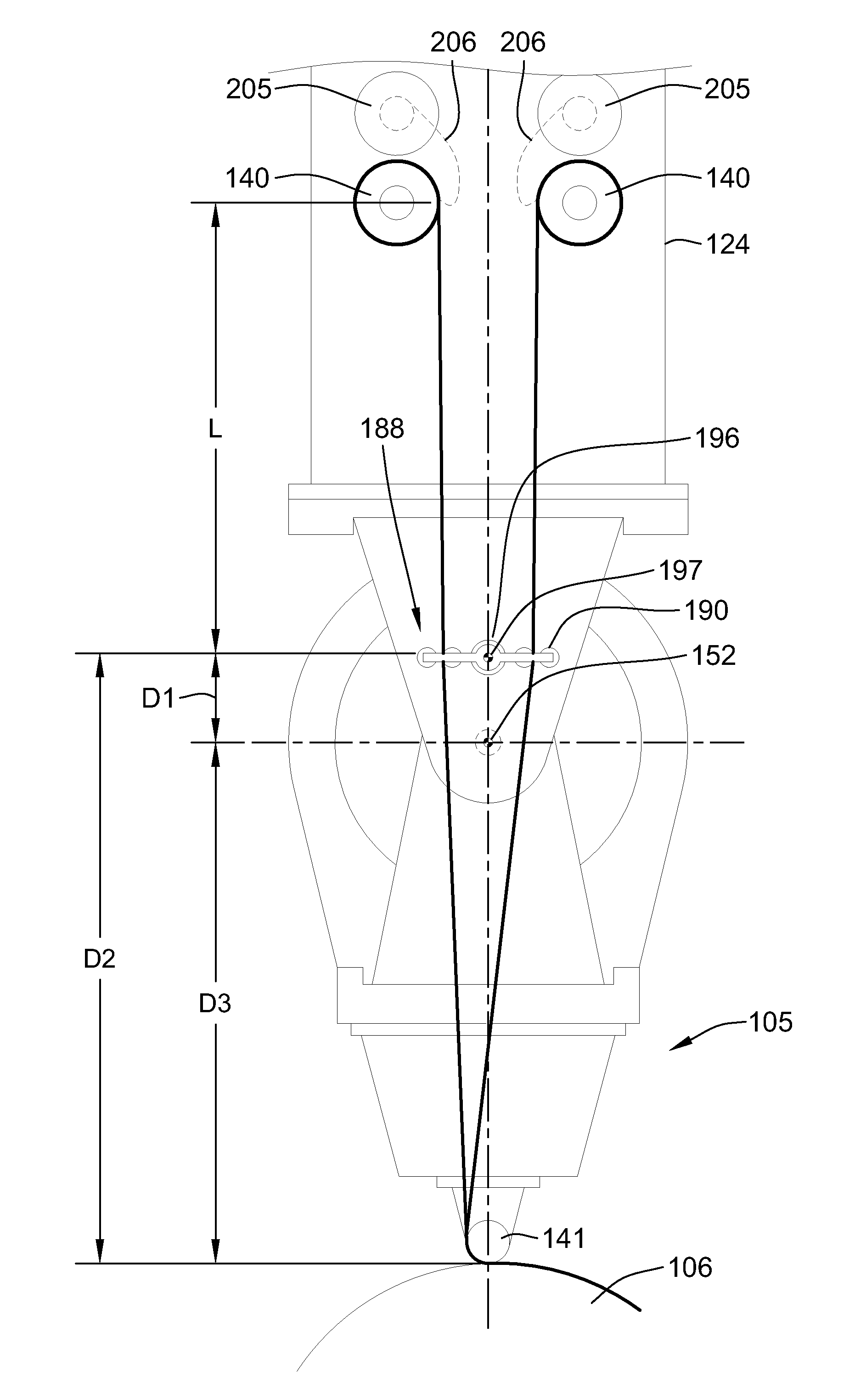
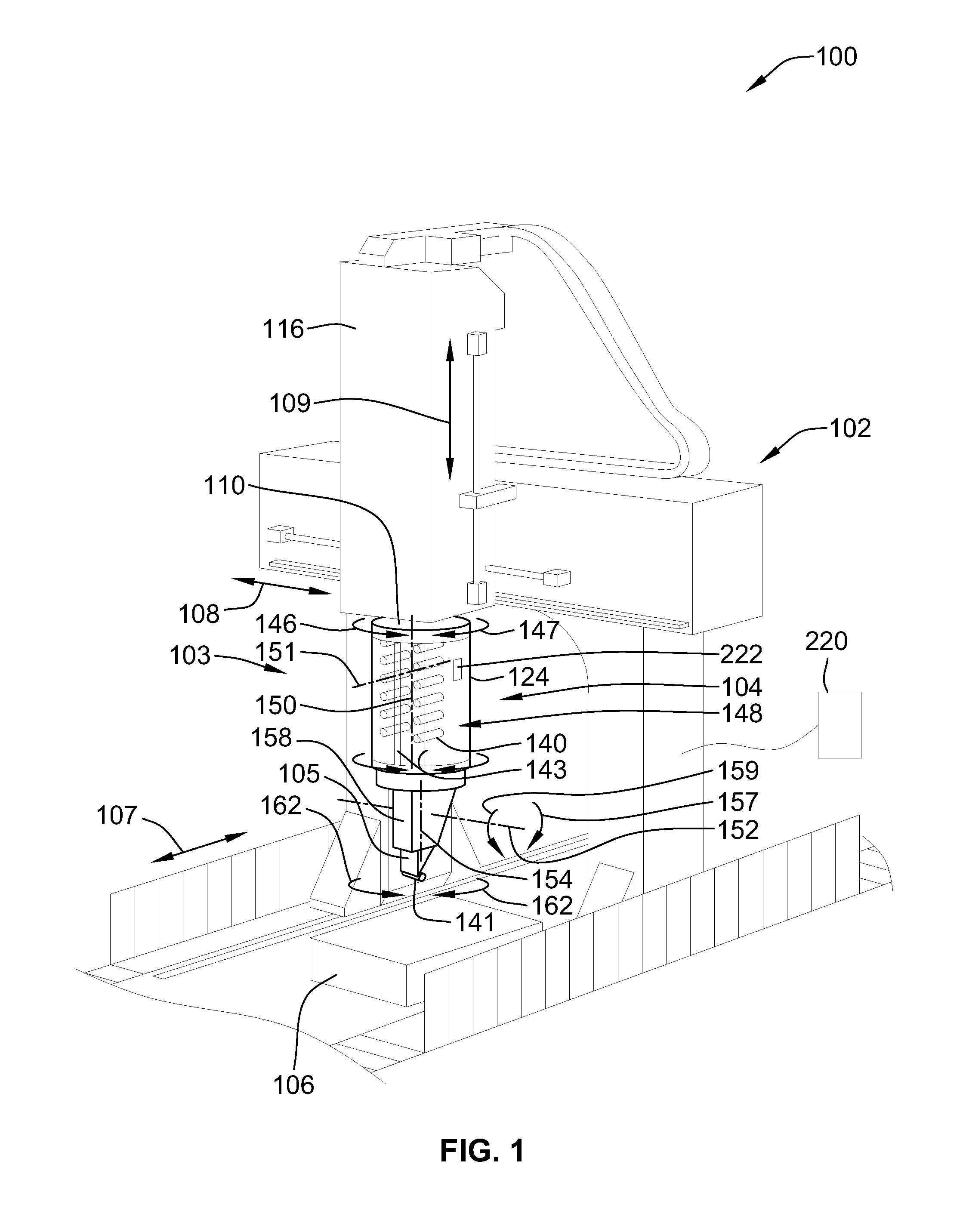
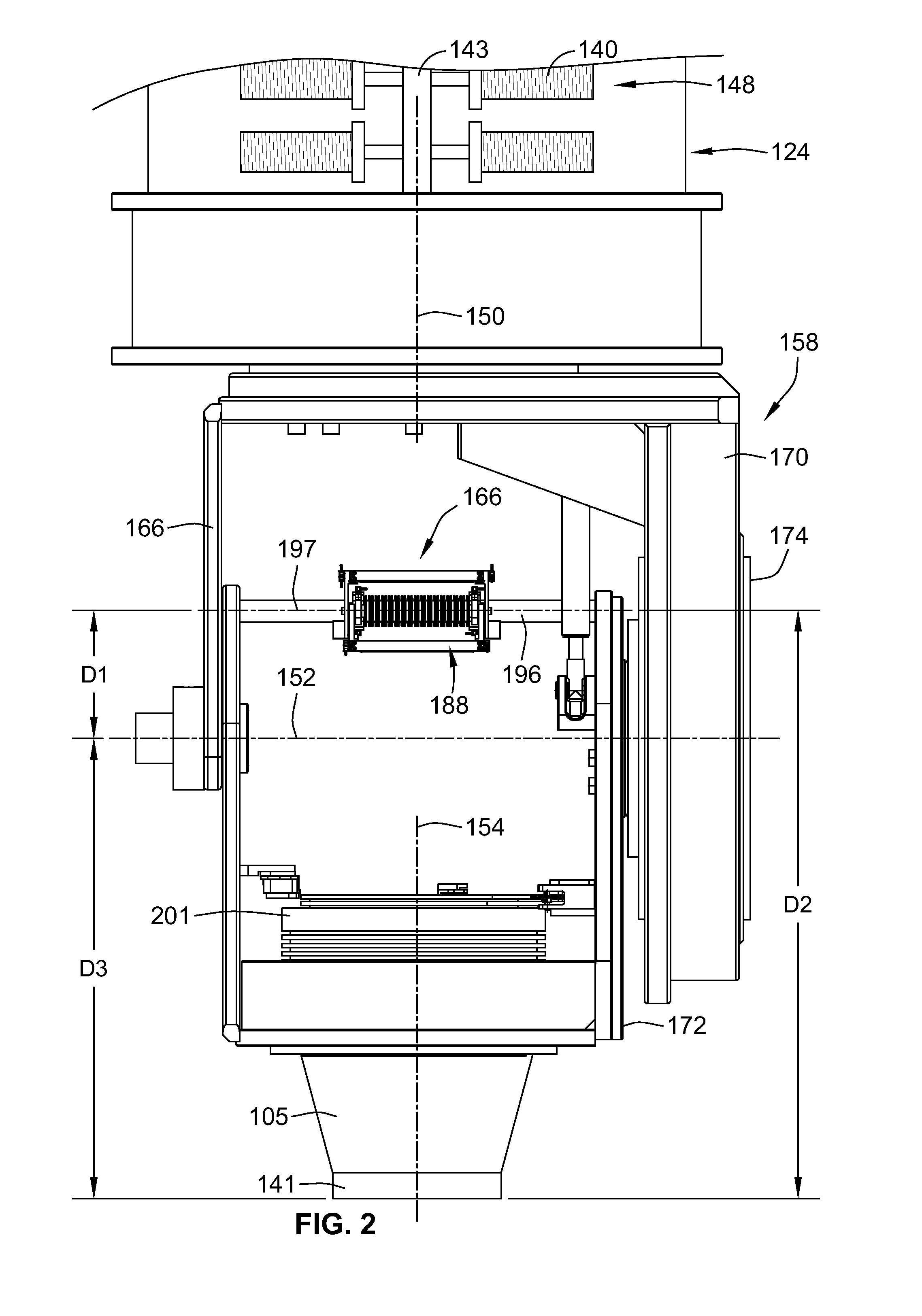
[0045]FIG. 1 illustrates an embodiment of a fiber placement system 100 according to an embodiment of the present invention. The fiber placement system 100 generally includes a positioning system in the form of gantry system 102 and an end effector attached to the gantry system in the form of a fiber delivery apparatus 103 (also referred to as a “creel and fiber placement head assembly”). The fiber delivery apparatus 103 includes a self-contained creel assembly 104 (hereinafter creel assembly 104) and a fiber placement head 105. The fiber placement system 100 is used to layup fiber tows onto a tool 106 to form composited parts....


PUM

PropertyMeasurementUnit
Angleaaaaaaaaaa
Diameteraaaaaaaaaa
Lengthaaaaaaaaaa

Abstract

A fiber placement system including positioner and a fiber delivery apparatus having a creel assembly and a fiber placement head is provided. The positioner moves the entire fiber delivery apparatus including the creel assembly and the fiber placement head via at least three linear degrees of freedom. The fiber delivery apparatus includes an articulating wrist for moving the fiber placement head relative to the creel assembly. The fiber placement apparatus is substantially free of linear degrees of freedom within the fiber tow paths between the spools and the fiber placement head. One or more rotational degrees of freedom may be provided along the tow path. In one embodiment, the interface between the fiber delivery apparatus and the positioner is laterally offset such that a portion of the creel axially overlaps with vertical ram of the positioner.

Description

FIELD OF THE INVENTION[0001]This invention generally relates to automated composite fiber placement manufacturing apparatuses and methods.BACKGROUND OF THE INVENTION[0002]In the practice of composite fiber manufacturing, the common method has been the utilization of a plurality of thin, narrow strips of material, embedded with a variety of chemical elements, applied in repetitive applications or “lay-ups” onto a fixed or moving surface. The strips of chemically embedded material are commonly referred to as “tows” and a collection of tows in a wider, multiple tow presentation may be referred to as “tape.” In either case, tow or tape applications in multiple layers and repeated lay-ups are cause for the build-up of material that, when processed through an autoclave under closely monitored and controlled atmospheric conditions, yield a solid “composite” material of substantial strength, yet light in weight.[0003]Accordingly, composite fiber placement manufacturing relies upon a fiber p...

Claims


Application Information

Patent Timeline
IPC IPC(8): B32B37/16B65H49/04
CPCY10T156/1785Y10T156/1348B29C70/384B23B31/42F16J15/46B23B2260/126B23B2270/027B23B2270/09B65H75/2437
Inventor OLDANI, TINOHOFFMANN, KLAUSDENT, WILLIAM R.
Owner INGERSOLL MACHINE TOOLS
Why Eureka
Try Eureka