Revolving transport device having an improved drive concept

a technology of rotating transport device and drive concept, which is applied in the direction of dynamo-electric components, dynamo-electric machines, non-mechanical conveyors, etc., can solve the problems of reducing the conveying speed in the curve region, requiring large distances between individual movers, and undesirable disturbances

Inactive Publication Date: 2012-04-19
SYNTEGON TECHNOLOGY GMBH
View PDF7 Cites 4 Cited by
  • Summary
  • Abstract
  • Description
  • Claims
  • Application Information

AI Technical Summary

Benefits of technology

[0010]An odd number of permanent magnets per row of permanent magnets provided are especially preferably arranged on each mover of the transport device. Said permanent magnets are thereby arranged such that a north pole or a south pole is alternately provided; thus enabling a first and a last permanent magnet of each row, which are arranged in the running direction of the mover, to have the same polarity. When using a plurality of movers, mutual repulsion of successive movers is consequently achieved due to

Problems solved by technology

The arrangement of the coils disclosed in this case reduces the conveying speed in the curve region so that

Method used


Image

  • Revolving transport device having an improved drive concept
  • Revolving transport device having an improved drive concept
  • Revolving transport device having an improved drive concept

Examples


Embodiment Construction

[0016]A transport device 1 according to a preferred exemplary embodiment of the invention is described in detail below with reference to FIGS. 1 and 2.

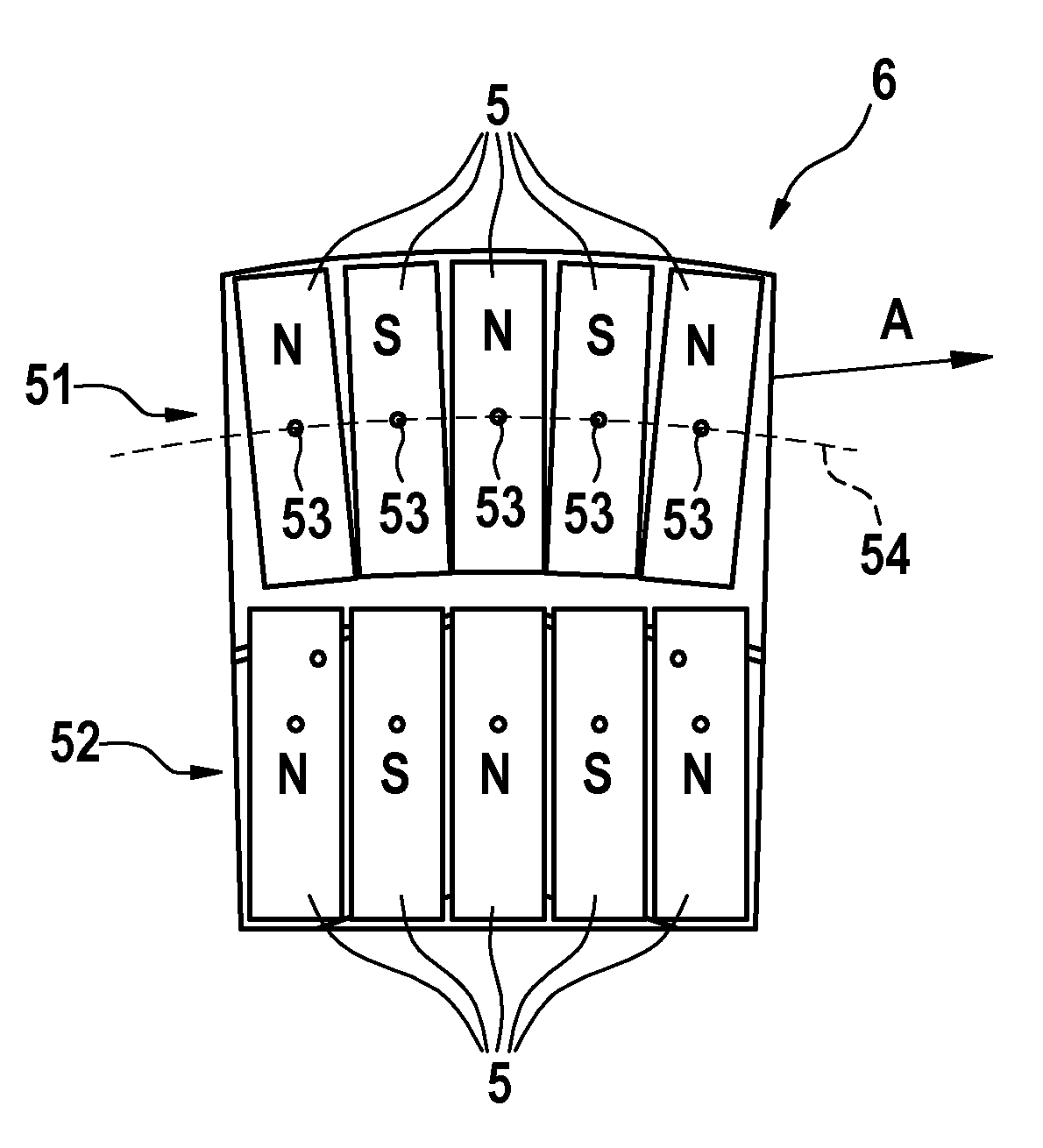
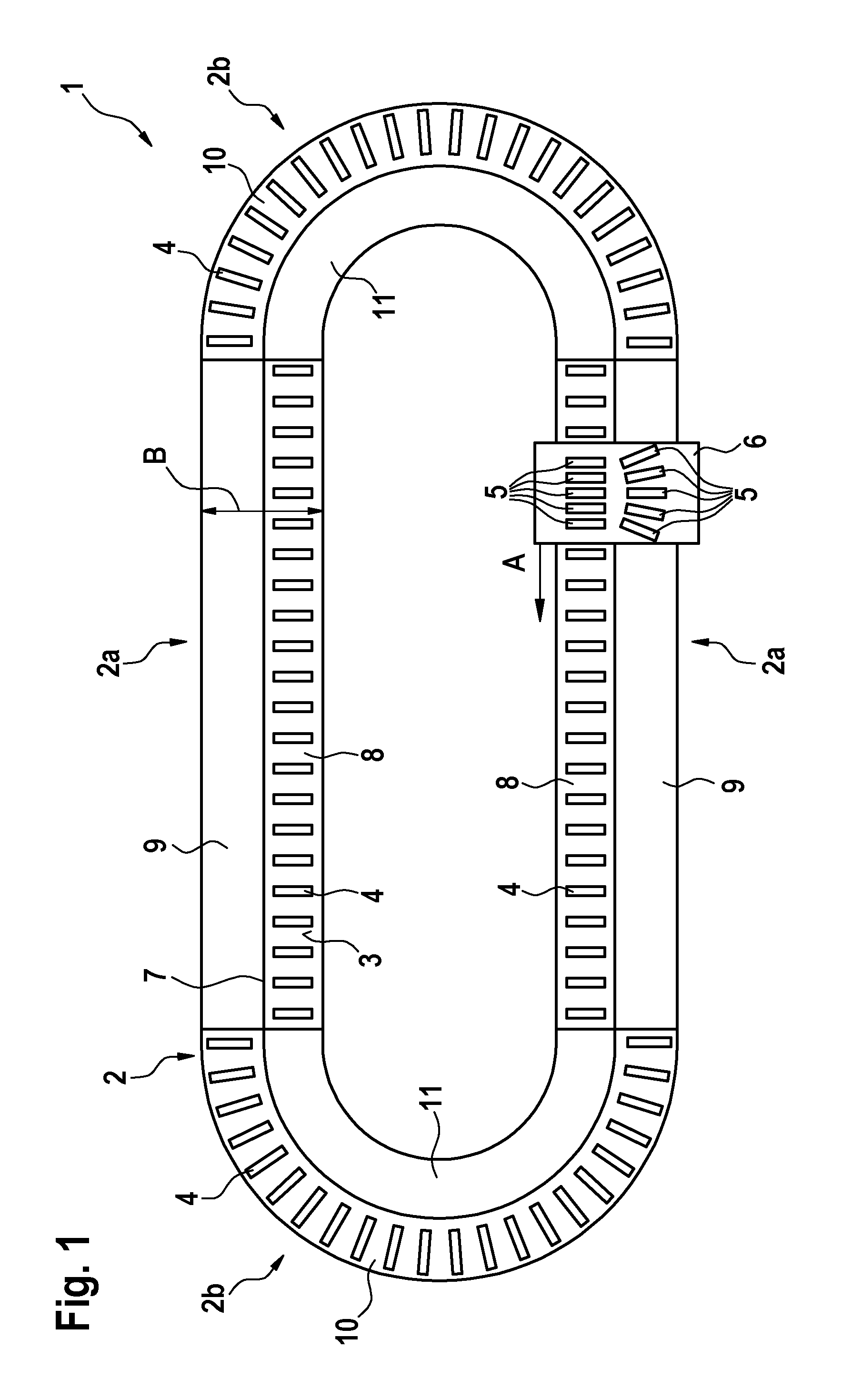
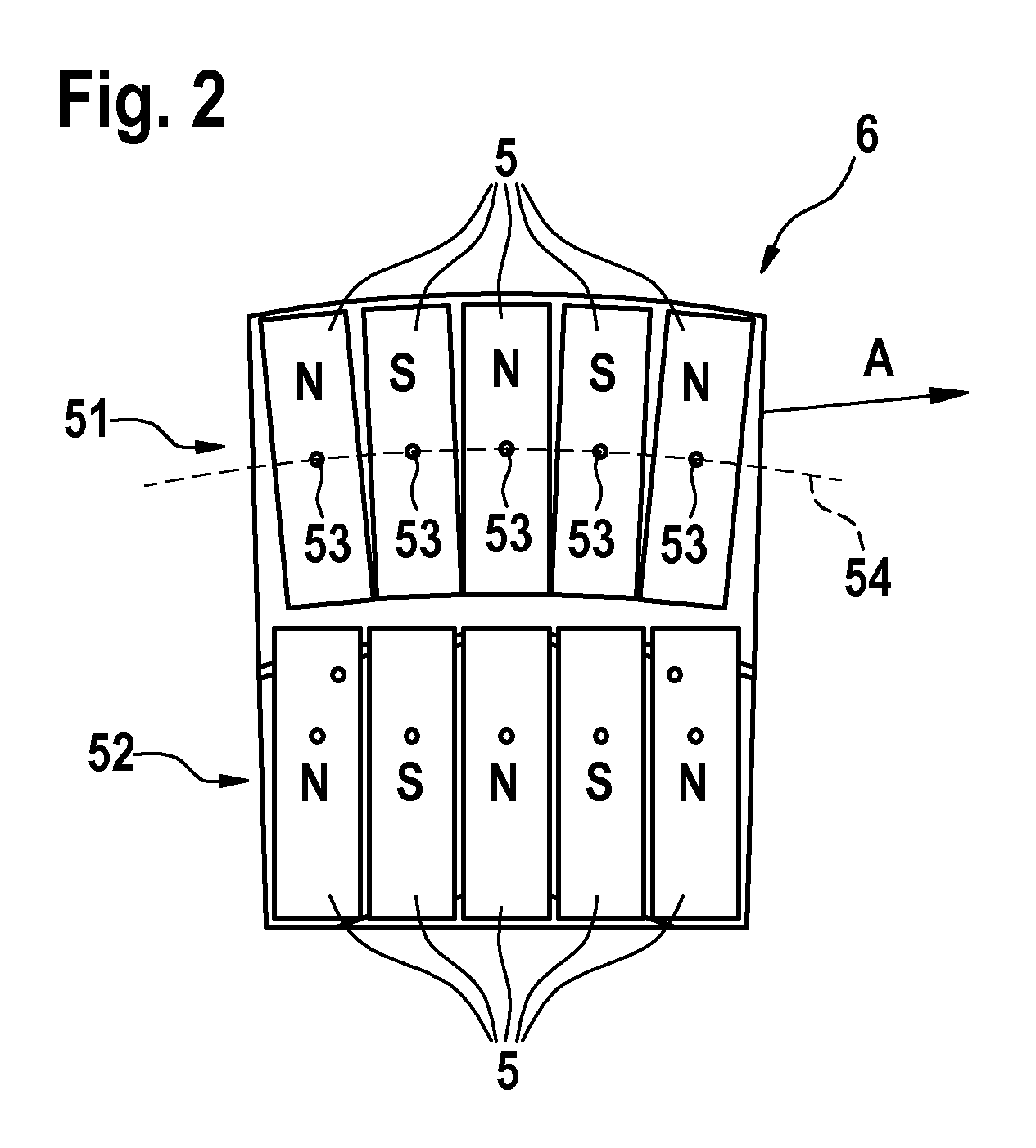
[0017]As can be seen in FIG. 1, the transport device 1 comprises a revolving transport section 2 having two linear regions 2a, which in each case are connected to one another via two curve regions 2b. A plurality of movers 6 is guided on the transport section; however, for the sake of clarity, only one mover is depicted in FIG. 1. The movers can thereby directly or indirectly convey products (not depicted). An electromagnetic drive is provided between the revolving transport section 2 and the movers 6. As can be seen in FIG. 1, the electromagnetic drive comprises a plurality of coil elements 4, which are successively arranged in the running direction. A carrier surface is denoted with the reference numeral 3. Furthermore, a plurality of permanent magnets 5 is arranged on each of the movers 6. As a result, the movers 6 can be moved alo...


PUM


Abstract

The invention relates to a transport device, in particular for charging packaging machines, comprising a revolving transport section having a linear region (2a) and a curve region (2b), an electromagnetic drive having a plurality of stationary coil elements (4) and a plurality of permanent magnets (5), wherein the stationary coil elements (4) are arranged on the transport section (2), and at least one mover (6), which is movably arranged on the revolving transport section (2) and can be moved by way of electromagnetic forces. The permanent magnets (5) are arranged on the mover (6), wherein a first row (51) of permanent magnets (5) and a second row (52) of permanent magnets (5) are arranged on the mover (6), wherein the first row (51) and the second row (52) of the permanent magnets are successively arranged in a miming direction (A) of the mover (6), and wherein the revolving transport section (2) has first coil regions (10), which are exclusively operatively connected to the first row (51) of permanent magnets (5) on the mover (6), and second coil regions (8), which are exclusively operatively connected to the second row (52) of permanent magnets (5) on the mover (6).

Description

BACKGROUND OF THE INVENTION[0001]The present invention relates to a revolving transport device.[0002]Revolving transport devices are known from prior art in different configurations. The U.S. Pat. No. 6,876,107 B2 constitutes a revolving transport device, in which a plurality of coils are arranged on the transport section. The coils are thereby arranged directly adjacent to one another and are configured in a curve region of the transport section such that a direct side-by-side arrangement is ensured there. In so doing, said coils have in plan view a shape which follows the inside of the curve.[0003]The effort is made with revolving transport devices to select a curve radius as small as possible in order to ensure a compact design. It is in fact possible with the coil arrangement proposed in the U.S. Pat. No. 6,876,107 B2 for the movers to move at a constant speed on the straight transport section, however, not in the curve region. The arrangement of the coils disclosed in this case...

Claims


Application Information

Patent Timeline
IPC IPC(8): B65G23/18B65G15/00
CPCB65G54/02H02K41/031H02K16/00
Inventor VAN DE LOECHT, HEINRICHREINISCH, MARTINVOELZ, KARSTEN
Owner SYNTEGON TECHNOLOGY GMBH
Why Eureka
Try Eureka