Solder pot

a technology of soldering pot and soldering cylinder, which is applied in the direction of soldering apparatus, manufacturing tools, welding/cutting media/materials, etc., can solve the problems of damage to the soldering components, short circuits, and inability to obtain the correct soldering joint, and achieve the effect of increasing the safety of the personnel tasked with implementing the process

Inactive Publication Date: 2012-04-19
ROBERT BOSCH GMBH
View PDF20 Cites 1 Cited by
  • Summary
  • Abstract
  • Description
  • Claims
  • Application Information

AI Technical Summary

Benefits of technology

[0063]As a corollary, the safety of personnel tasked with implementing the process is also notably increased.

Problems solved by technology

The capillary-action soldering process is subject to malfunctions that may have various origins, in particular the temperature of the solder, which, if it is colder than the printed circuit board and the pins of the electronic components to be soldered, cannot rise by capillary action into the plated through-holes holes, so that it is then impossible to obtain a correct solder joint.
However, it is not possible to choose any geometry in that it is necessary to take into account, in each particular case, regions called “taboo” regions, i.e. free regions around each of the pins of the electronic components to be soldered, so as in particular to remove any risk of the solder making contact with neighbouring electronic components already fixed onto the printed circuit board, contact being liable to damage these components or cause short circuits.
The major problem encountered in selective soldering using pots is however related to the wettability of the surface of the solder pots by the solder.
However, as soon as the pots are immersed in the solder bath, the temperature of which is 300° C.-325° C., the pure tin layer covering the new pots melts and completely disappears; the solder then makes direct contact with a 20 μm thick FexSny layer and the steel / tin interface becomes irregular.
This layer is wettable when the pots are new but, over the course of their use, this layer thicken and becomes irregular because tin diffuses from the solder into the steel and because oxide layers appear on the surface of the pots, thereby making these surfaces passive and consequently causing them to lose their wettability.
This preventive cleaning operation is carried out manually using brushes and is particularly awkward due to the small size of the pots and the presence of dead zones which are difficult to reach and is furthermore dangerous in that it must be carried out in a hot zone, thereby obliging personnel to take specific precautions and to wear protective means such as helmets, visors, etc.
These demanding preventative measures do not however make it possible to meet the desired quality requirements, which are becoming increasingly strict, and very many soldering defects are still observed, in particular critical soldering defects such as unsoldered points, problems in the wicking of solder into the plated through-holes holes, overflow of the solder onto the top side of the printed circuit board and onto neighbouring electronic components.

Method used


Image

  • Solder pot
  • Solder pot

Examples


Embodiment Construction

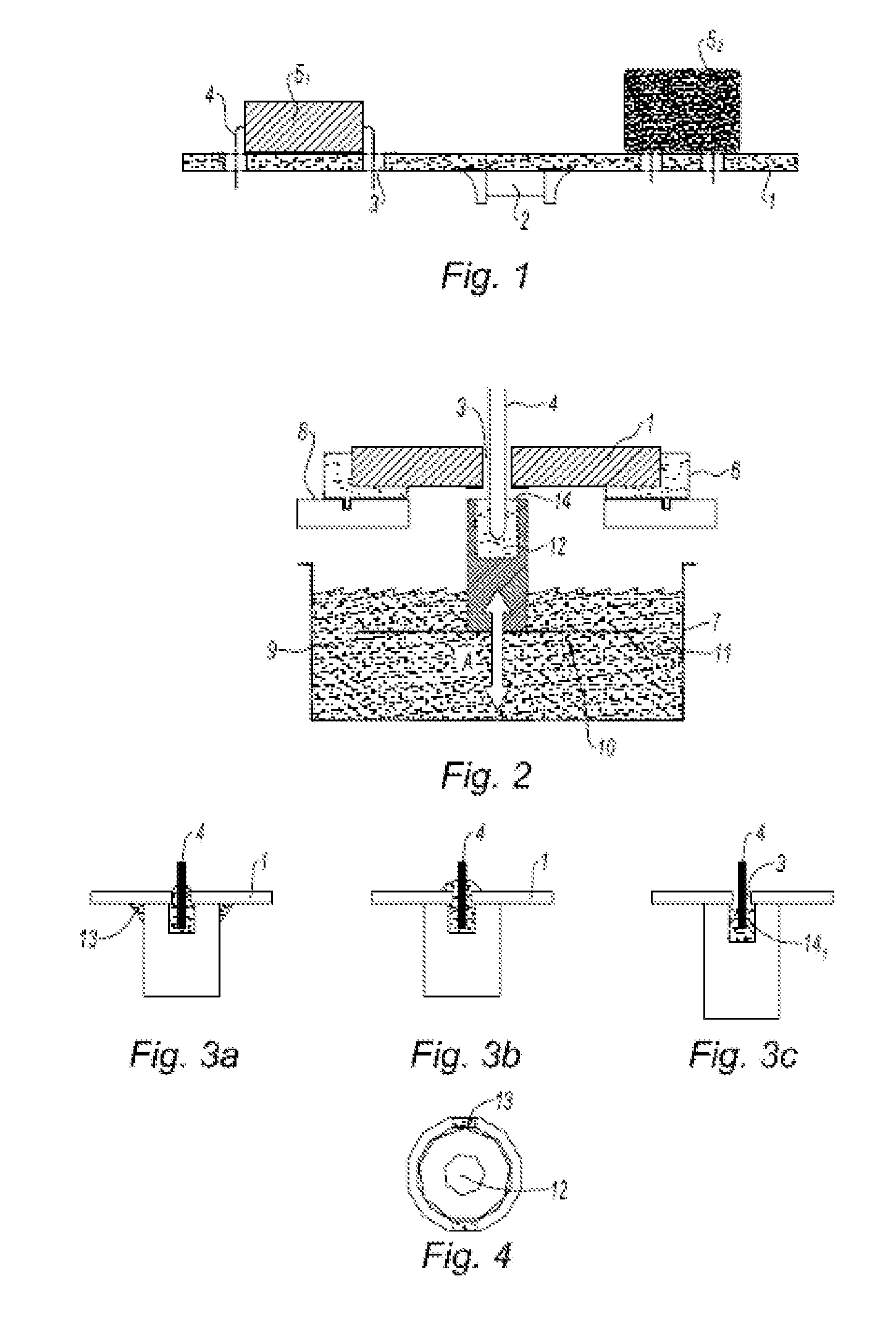
[0069]According to FIG. 1, the printed circuit board 1 bears an electronic component 2 already fixed to its top side, and is pierced with plated throughholes holes 3 into which the pins 4 of two components to be soldered 51 and 52, positioned on its top side, are inserted.

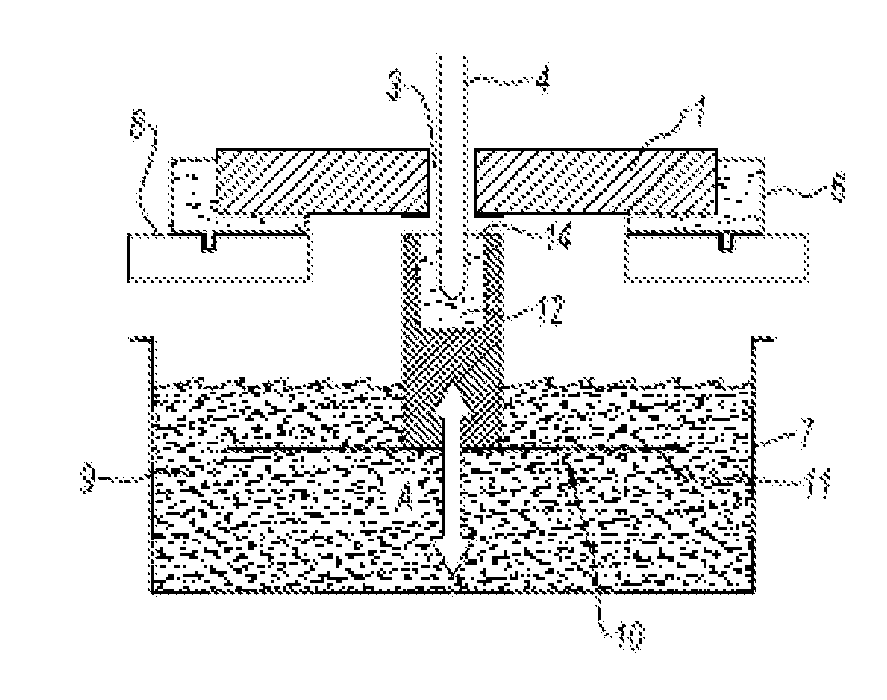
[0070]In FIG. 2, the printed circuit board 1 is shown schematically as a single pin 4 and is shown in the soldering position.

[0071]This printed circuit board 1 is placed on a holder 6 and is subjected beforehand to fluxing and preheating steps.

[0072]The soldering zone, which is also shown schematically, consists of a tank 7, closed from above using a specific plate 8 and a cover, the role of which is to keep the tank sealed outside of a soldering cycle.

[0073]The tank 7 is filled with solder 9, consisting of 63% tin and 37% lead, kept at a temperature of about 300° C. to 325° C. under a neutral atmosphere.

[0074]The tank 7 moreover contains a soldering matrix 10 consisting of a supporting plate 11 bearing a set of so...


PUM

PropertyMeasurementUnit
temperatureaaaaaaaaaa
melting pointaaaaaaaaaa

Abstract

Solder pot intended for a machine for selective soldering of through-hole electronic components on a printed circuit board, characterized in that it is in the form of a right prism, preferably with a hexagonal base.

Description

BACKGROUND OF THE INVENTION[0001]The present invention relates to a solder pot intended for a machine for selective soldering of through-hole electronic components on a printed circuit board, and to a process employing such a pot.[0002]A printed circuit board is a punched, perforated or countersunk rigid substrate on which there are surface-mounted electronic components (called SMCs), connected on one or both of its sides, and electroplated holes that are used for the insertion of the pins of through-hole components to be soldered—there may be any number of these components.[0003]The printed circuit board is a two-part component: one part is called the “insulating” part and the other part is called the “conducting” part.[0004]The insulating part, called a “prepreg”, consists of a resin-impregnated reinforcement. This reinforcement is often made of fibre glass and takes the form of a woven fabric, but it may also be made of quartz, or of synthetic fibres sold under the Kevlar tradema...

Claims


Application Information

Patent Timeline
Patent Type & Authority Applications(United States)
IPC IPC(8): B23K1/20B23K3/06
CPCB23K3/0607H05K3/3447H05K2203/0763H05K2203/0195H05K3/3468
Inventor ELHAGE, BASSEM
Owner ROBERT BOSCH GMBH
Why Eureka
Try Eureka