
Power unit for an electrical steering system
- Summary
- Abstract
- Description
- Claims
- Application Information
AI Technical Summary
Benefits of technology
Problems solved by technology
Method used
Image

Examples
Embodiment Construction
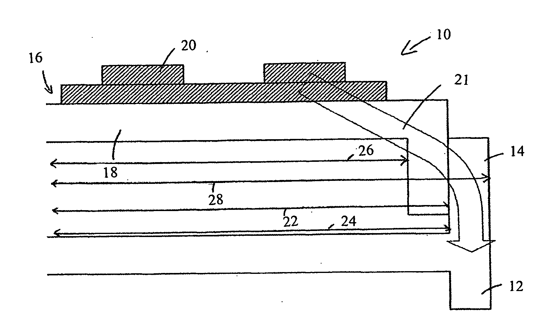
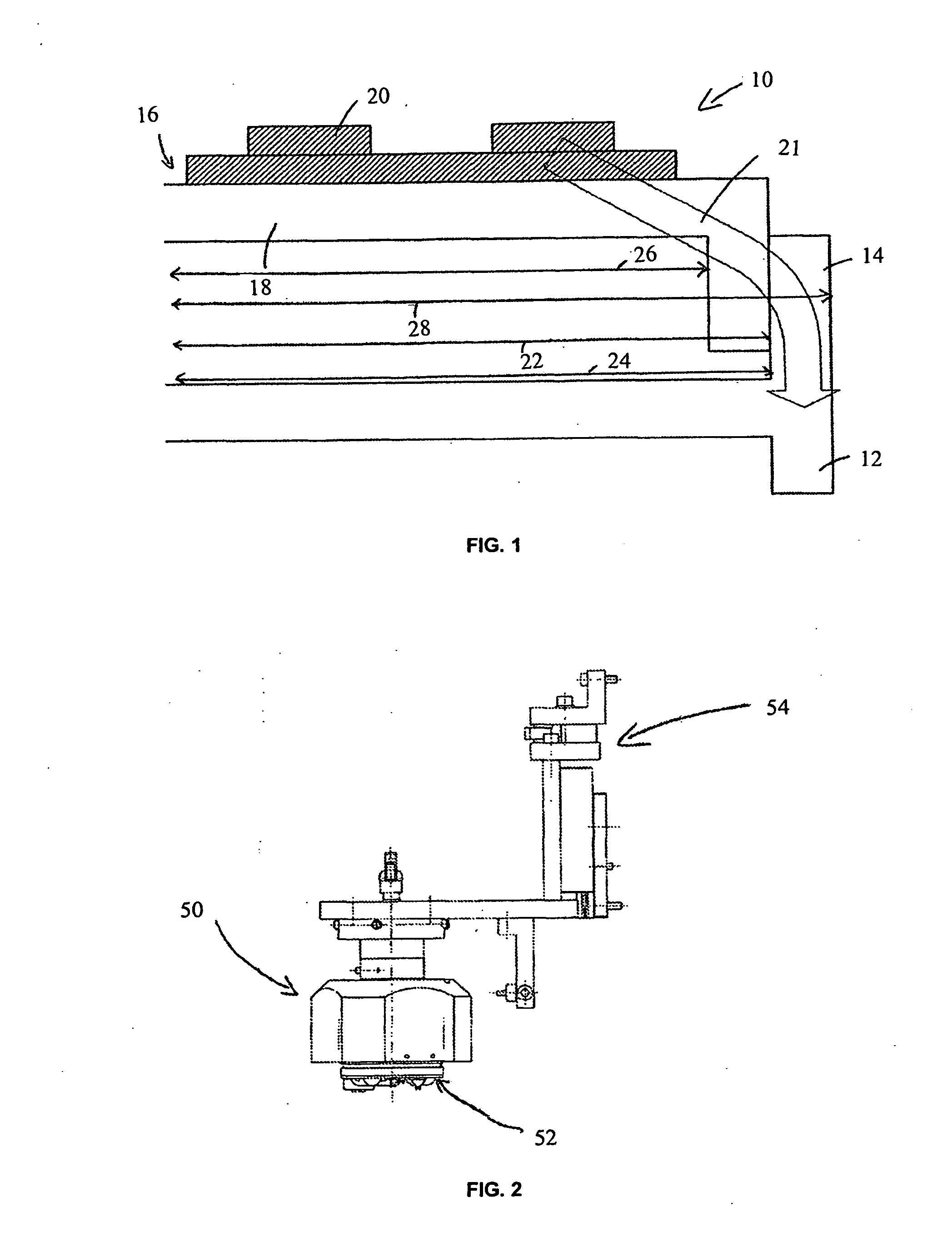
[0027]FIG. 1 shows an embodiment of a power unit, which is denoted in the overall by reference numeral 10. A housing 12 of a motor, which is not shown in detail, can be seen, the motor being used in an electric steering system. This motor housing 12 has an upwardly extending flange 14, which is closed as viewed from above and thus has a circular shape.
[0028]A control unit 16 having a base plate 18 and an output stage 20 located thereon is inserted in the motor housing 12. This base plate 18 is inserted into the motor housing 12 and connected thereto by shrink fitting. During operation, the output stage 20 generates heat and gives off the same to the motor housing 12, as indicated by the arrow 21.
[0029]The base plate 18 of the control unit 16 is dimensioned such that it has a larger diameter than the motor housing 12 in the region of the flange 14. Dimensioning the diameter of the base plate 18 at approximately 0.03 to 0.1 mm larger than the diameter of the motor housing is an obviou...
PUM
| Property | Measurement | Unit |
|---|---|---|
| Temperature | aaaaa | aaaaa |
| Temperature | aaaaa | aaaaa |
| Temperature | aaaaa | aaaaa |
Abstract
Description
Claims
Application Information