

Minisize mould device for precise compound forming of minisize double gears
A compound forming and double gear technology, applied in forming tools, forging/pressing/hammer devices, wheels, etc., can solve the problems of cumbersome double gear process and high cost of double gear processing
- Summary
- Abstract
- Description
- Claims
- Application Information
AI Technical Summary
Problems solved by technology
Method used
Image

Examples
specific Embodiment approach 1
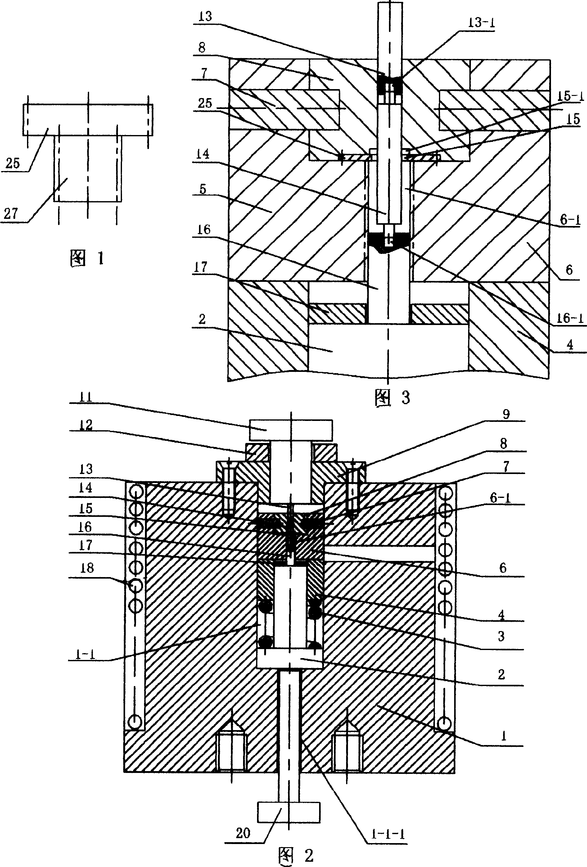
[0005] Specific Embodiment 1: The present embodiment will be specifically described below with reference to FIG. 2 and FIG. 3 . This embodiment consists of a mold base 1, a top column 2, a spring 3, a slider 4, a die 6, a punch 16, a punch guide sleeve 9, a punch 11, a limit ring 12, an electric heating ring 18 and an ejector rod. 20. The upper insert 8, the upper punch 13 and the pin 7 are composed. The center of the mold base 1 has a stepped through hole 1-1 with a large upper part and a smaller one, and a threaded hole is opened at the lower end of the stepped through hole 1-1. 1-1-1, the upper end of the ejector rod 20 is screwed into the threaded hole 1-1-1, and the ejector rod 2 with an inverted "T"-shaped longitudinal section is set in the stepped through hole 1-1 to eject the rod 20 Above, the slider 4 is set on the outer circular surface of the small diameter end of the top column 2, the spring 3 is arranged between the upper end surface of the large diameter end of t...
specific Embodiment approach 2
[0006] Specific Embodiment 2: The present embodiment will be specifically described below in conjunction with FIG. 2 and FIG. 3 . The difference between this embodiment and the first embodiment is that it also includes a backing ring 17 which is arranged between the lower end surface of the die 6 and the upper end surface of the top post 2 . In this way, the forming of the micro-double gear can be divided into two steps in order to ensure the forming accuracy. The first step requires setting the backing ring 17 in the mold set, this step being the pre-forming stage. Mold, gear 25 and blank 14 are assembled, and punch 16 is installed in the toothed hole of die 6 bottoms, and punch 16 has only a small part in die 6. The upper end surface of the backing ring 17 is in contact with the lower end surface of the die 6 . The force applying mechanism of the forming equipment is pressed on the punch 11, and the punch 11 is pressed on the upper punch 13, and the upper punch 13 is press...
specific Embodiment approach 3
[0007] Specific Embodiment Three: The present embodiment will be specifically described below in conjunction with FIG. 3 . The difference between this embodiment and the first embodiment is: the lower end surface of the upper punch 13 is provided with a first blind hole 13-1 coaxial with the upper punch 13, and the upper end surface of the punch 16 is provided with a convex hole 13-1. The second blind hole 16-1 of mold 16 coaxial. In this way, the blank 14 is filled into the first blind hole 13-1 and the second blind hole 16-1 during the deformation process to form the gear shaft of the micro double gear, which simplifies the assembly work. In this embodiment, a thin shaft can also be placed in the first blind hole 13-1 and the second blind hole 16-1, and the shaft extends out of the hole for a certain length. The reaction force upon deformation secures the shaft within the microgear part being formed. The advantage of doing this is that the shaft is also formed while comple...
PUM
| Property | Measurement | Unit |
|---|---|---|
| diameter | aaaaa | aaaaa |
| thickness | aaaaa | aaaaa |
| thickness | aaaaa | aaaaa |
Abstract
Description
Claims
Application Information