Electric Field Signature Detection Using Exciter-Sensor Arrays

an electric field and sensor array technology, applied in the field of detection of objects, can solve the problems of not being able to discern and further process, the influence of non-charged/uncharged (neutral) insulating and conductive bodies or objects on electrostatic fields, and not being investigated as thoroughly

Inactive Publication Date: 2012-04-19
RAMPART DETECTION SYST
View PDF11 Cites 31 Cited by
  • Summary
  • Abstract
  • Description
  • Claims
  • Application Information

AI Technical Summary

Benefits of technology

[0020]In accordance with the present invention, there is provided an electric field signature detector for detecting and identifying objects comprising a high voltage exciter electrically coupled to an antenna for providing an electrostatic field; a sensor for detecting an electrostatic signature resulting from interaction of an object being detected with an electrostatic field being generated by the high voltage exciter; the sensor comprising an amplifier, an antenna electrically coupled to an input of the amplifier, and an output of the amplifier electrically coupled to an analog to digital converter and processor.

Problems solved by technology

None of these attempts have been able to discern and further process the small but vitally important electric field changes that are the unique signatures of objects to be detected.
The interaction with and influence on electrostatic fields by noncharged / uncharged (neutral) insulating and conductive bodies or objects has not been investigated as thoroughly as the above, and is less well understood.
Further, an aircraft will generate a significant charge buildup in flight.
The sensing of the weak alterations in the electrostatic field is extremely difficult, as ideally one is sensing charge displacement (due to potential gradients), not direct potential (as there is no contact, nor continuous current flow, as in ionic discharge currents).
However, these require a reference to earth ground (or a virtual ground) and further, suffer from distributed capacitance effects and similar anomalies.

Method used


Image

  • Electric Field Signature Detection Using Exciter-Sensor Arrays
  • Electric Field Signature Detection Using Exciter-Sensor Arrays
  • Electric Field Signature Detection Using Exciter-Sensor Arrays

Examples


Embodiment Construction

[0045]For a general understanding of the present invention, reference is made to the drawings. In the drawings, like reference numerals have been used throughout to designate identical elements.

[0046]The present invention will be described by way of example, and not limitation. Modifications, improvements and additions to the invention described herein may be determined after reading this specification and viewing the accompanying drawings; such modifications, improvements, and additions being considered included in the spirit and broad scope of the present invention and its various embodiments described or envisioned herein.

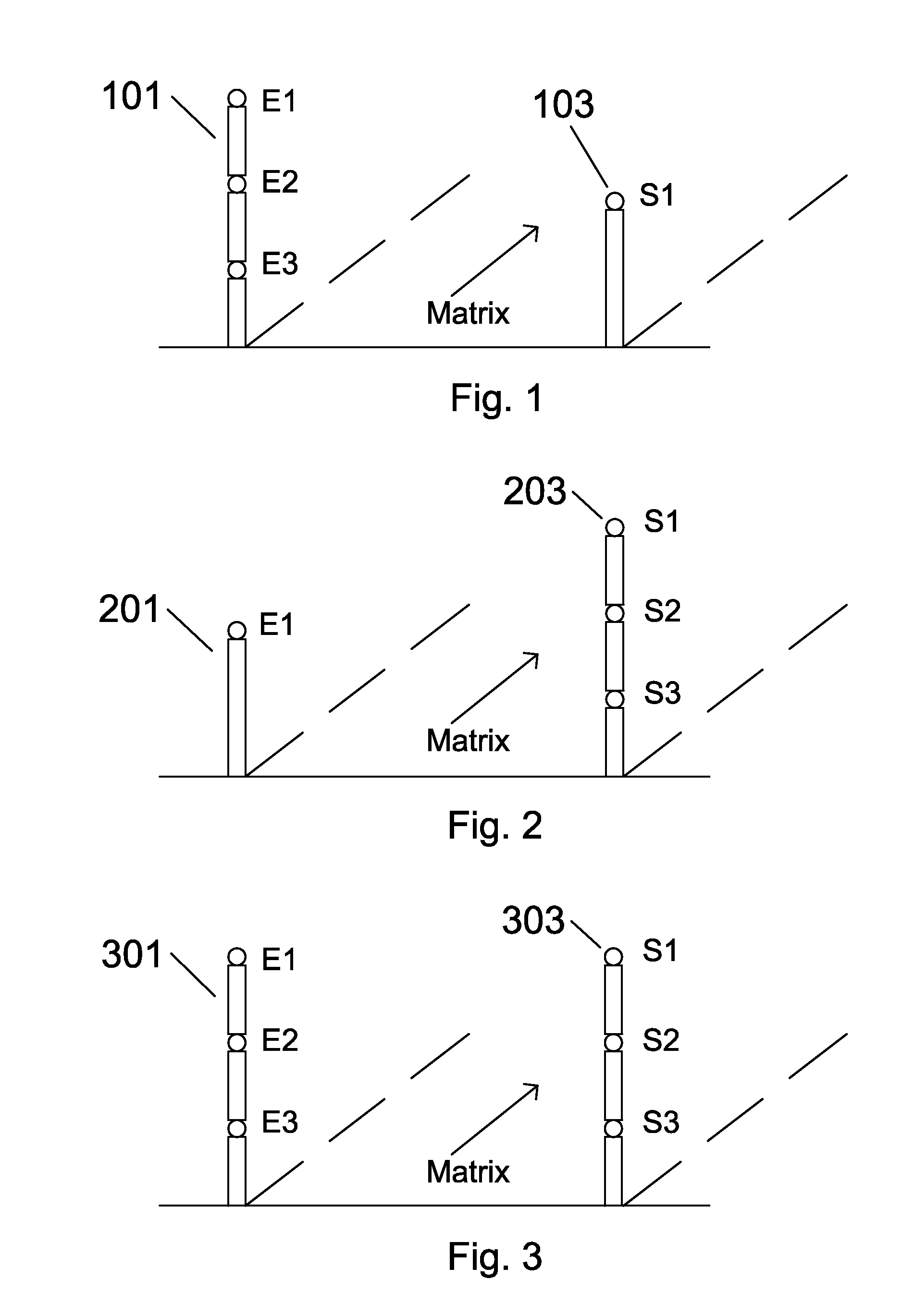
[0047]FIGS. 1, 2, and 3 depict various topologies of the sensor and exciter array.

[0048]Referring first to FIG. 1, there is illustrated an array of vertical electrostatic excitation nodes E1, E2 and E3, shown as 101, and electrostatic sensing node S1 depicted as 103. In the example of FIG. 1, for every sensor there are a multitude of exciters.

[0049]By way of exa...


PUM


Abstract

An electric field signature detector for detecting and identifying objects that uses multiple electrostatic sensor nodes each having a passive sensing electrode whose free conduction electrons are displacement responsive to an externally applied or sensed electric field potential, and a transimpedance converter and amplifier exhibiting ultra-high input impedance for translating low level input displacement current from a sensing electrode into a useable output signal in response to a charge displacement signal induced on the passive sensing electrode by an external electric field. The electric field signature detector further includes an exciter for providing a reference electric field used in the retrieval and processing of an electric field signature representative of an object and class of object under investigation. The electric field signature detector having uses including military, security, anti-terrorist, and defense related.

Description

[0001]This application claims priority to U.S. patent application Ser. No. 61 / 331,596 filed May 5, 2010 entitled “Electric Field Signature Detection Using Exciter-Sensor Arrays” by Dieter Wolfgang Blum of Aldergrove, British Columbia, CANADA.BACKGROUND OF THE INVENTION[0002]1. Field of the Invention[0003]This invention relates generally to the detection of objects, and more particularly to an apparatus for the detection and identification of objects using electric field signature detection with exciter-sensor arrays.[0004]2. Description of Related Art[0005]Distortions in the electric field surrounding an object are typically caused by either emission of an electric field through the imbalance of charges, for example, the electric field surrounding a power line, electric motor, transformer, some plastics, and the like, or by the disruption of the isopotential lines of the earth's electric field when an object passes or is placed within the earth's natural potential gradient. Humans w...

Claims


Application Information

Patent Timeline
Patent Type & Authority Applications(United States)
IPC IPC(8): G01R29/12
CPCG01V3/088F41H11/136
Inventor BLUM, DIETER WOLFGANG
Owner RAMPART DETECTION SYST
Why Eureka
Try Eureka