All-fiber interferometric fiber optic gyroscope for inhibiting zero drift

a fiber optic gyroscope and interferometer technology, applied in the field of fiber optic sensing, can solve the problems of small zero drift and low accuracy

Inactive Publication Date: 2012-04-19
PEKING UNIV
View PDF5 Cites 15 Cited by
  • Summary
  • Abstract
  • Description
  • Claims
  • Application Information

AI Technical Summary

Benefits of technology

[0010]Introduced here is a method for inhibiting zero drift of all-fiber interferometric fiber optic gyroscopes and a corresponding all-fiber interferometric fiber optic gyroscope.
[0011]According to the characteristics of the zero drift of the open loop interferometric fiber optic gyroscope—namely, that it (1) is independent of the rotation direction of the gyroscope, and (2) changes slowly—the present invention performs high

Problems solved by technology

Zero drift may be caused by thermal sensitivity of the gyroscope components and/or other dynamic sources of error.
The advantages of the i

Method used


Image

  • All-fiber interferometric fiber optic gyroscope for inhibiting zero drift
  • All-fiber interferometric fiber optic gyroscope for inhibiting zero drift
  • All-fiber interferometric fiber optic gyroscope for inhibiting zero drift

Examples


Embodiment Construction

[0027]The present invention is further explained in detail below with reference to the drawings.

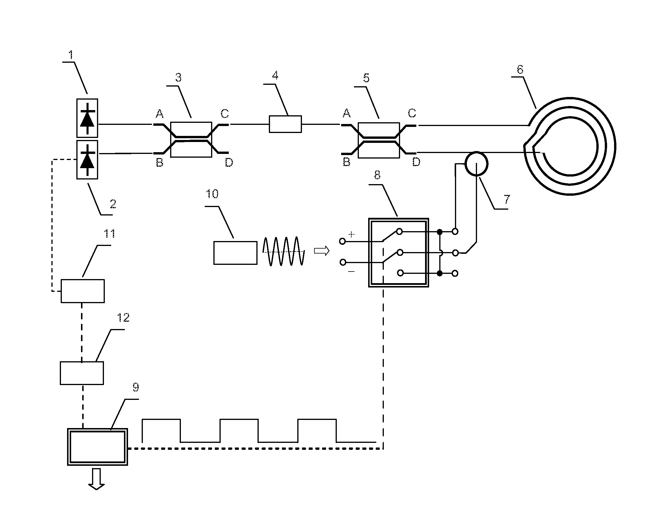
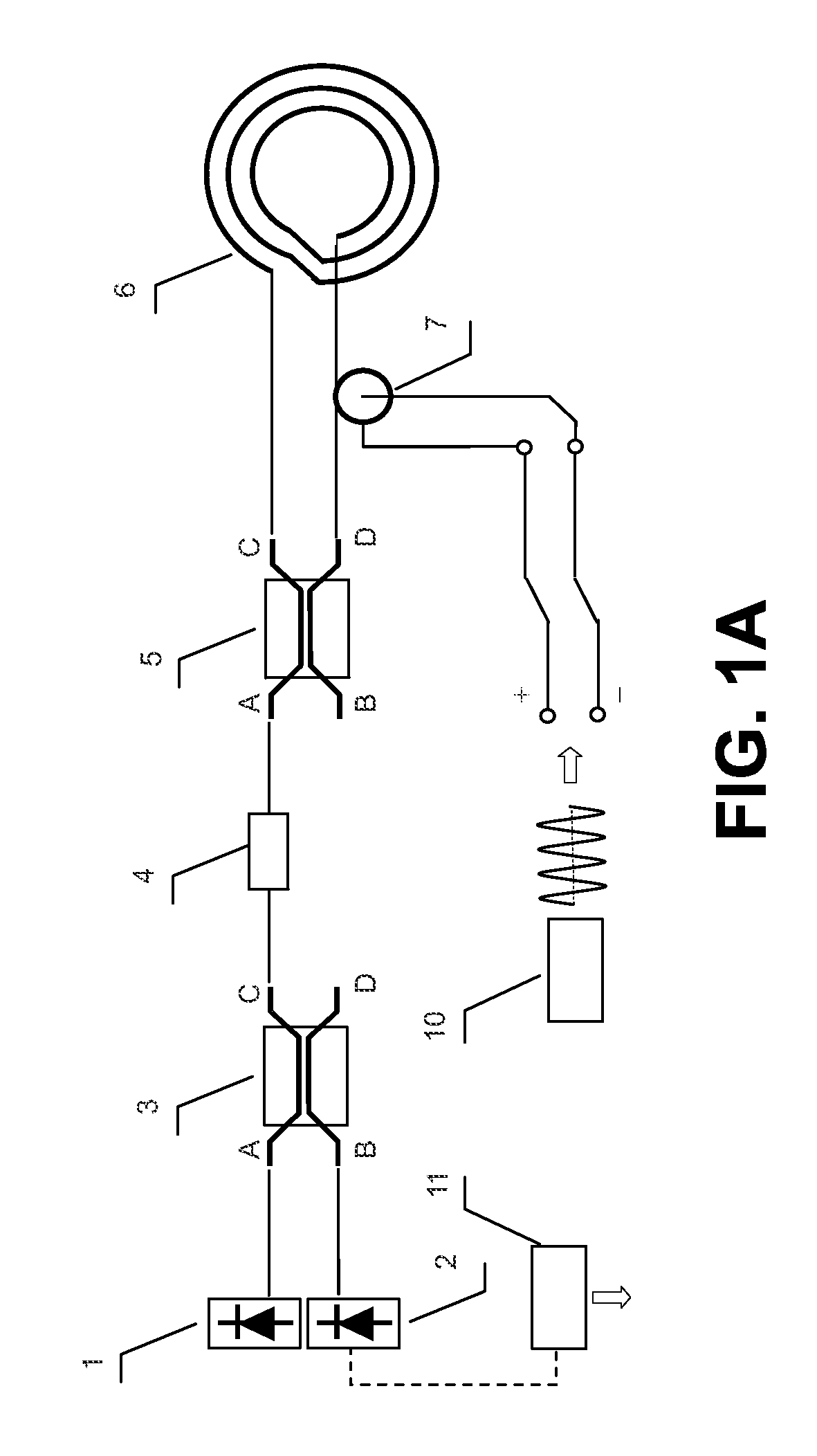
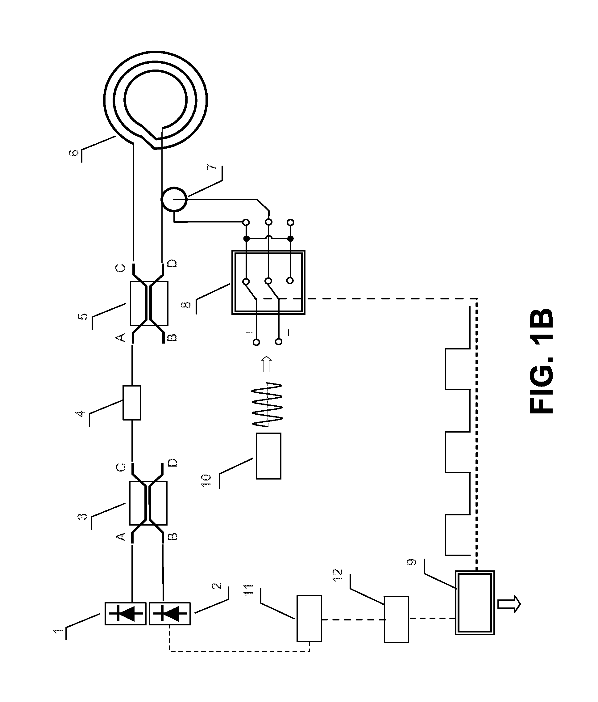
[0028]As shown in FIG. 1B, the all-fiber interferometric fiber optic gyroscope of one embodiment of the present invention comprises two parts:

[0029]The first part is a typical all-fiber interferometric fiber optic gyroscope, comprising a superluminescent diode 1, a photodetector diode 2, a light source coupler 3, a polarizer 4; a fiber optic loop coupler 5, a fiber optic loop 6, an oscillator 10, and a demodulation / amplifier circuit 11.

[0030]The second part is a set of circuit units, comprising a PZT piezoelectric ceramic phase modulator 7, a phase reversal switch 8, a DSP chip 9 and an analog-to-digital (A / D) converter 12.

[0031]The PZT piezoelectric ceramic phase modulator 7 is a cylindrical sheet. Part of the optical fiber of the fiber optic loop (e.g., about 1 meter) is wound around and bonded to the outer circle of the ceramic phase modulator 7. The AC voltage signal on the PZT piezoe...


PUM


Abstract

A method for inhibiting zero drift of an all-fiber interferometric fiber optic gyroscope and a corresponding all-fiber interferometric fiber optic gyroscope are disclosed. The method comprises: reversing the polarity of an AC voltage applied to a PZT piezoelectric ceramic phase modulator according to a predetermined half-cycle time period, and making half of the difference between output rotation rates of the gyroscope in two adjacent half-cycle time periods as the output rotation rate of the gyroscope in a cycle. A phase reversal switch and a DSP chip are added to the all-fiber interferometric fiber optic gyroscope. The phase reversal switch is used for controlling the polarity of the AC voltage, and the DSP chip is used for outputting a square wave signal to control the phase reversal switch and for calculating the output rotation rate of the gyroscope according to the output signal of a demodulation/amplifier circuit.

Description

[0001]This is a continuation of International Patent Application No. PCT / CN2010 / 001622, filed on Oct. 15, 2010 under the Patent Cooperation Treaty (PCT).FIELD OF THE INVENTION[0002]The present invention relates to all-fiber interferometric fiber optic gyroscopes, and in particular, it relates to technology for inhibiting zero drift of all-fiber interferometric fiber optic gyroscopes, which pertains to the technical field of fiber optic sensing.DESCRIPTION OF THE RELATED ART[0003]A gyroscope is an instrument for measuring angular velocity-angular displacement in inertial space, and its history can be traced back to thousands of years ago. Mechanical gyroscope, laser gyroscope and fiber-optic gyroscope are respectively called first, second and third generation gyroscopes. Fiber optic gyroscopes emerged in 1976 and mass production thereof was launched in the 1990s. The all-fiber interferometric fiber optic gyroscope is an important variety in the family of fiber optic gyroscope, and it...

Claims


Application Information

Patent Timeline
IPC IPC(8): G01C19/72
CPCG01C19/72
Inventor WANG, XINYUEHE, CHANGHONGWANG, ZIYU
Owner PEKING UNIV
Why Eureka
Try Eureka