
Cutting insert, cutting tool, and method of manufacturing machined product using the same

a cutting tool and cutting insert technology, applied in the direction of manufacturing tools, shaping cutters, transportation and packaging, etc., can solve the problems of difficult chip treatment and chip twisted, and achieve the effect of reducing twisting and being less susceptible to twisting

Active Publication Date: 2012-04-19
KYOCERA CORP
View PDF11 Cites 26 Cited by
  • Summary
  • Abstract
  • Description
  • Claims
  • Application Information

AI Technical Summary

Benefits of technology

[0004]An object of the present invention is to provide a cutting insert, particularly a negative type cutting insert having excellent chip discharge performance, a cutting tool, and a method of manufacturing a machined product using the same.
[0009]That is, with the cutting insert according to the embodiment of the present invention, the small width chips susceptible to twisting, which are generated when the amount of depth of cut is small, namely, when only the minor cutting edge is used, or when the vicinity of the boundary of the minor cutting edge and the major cutting edge is used mainly, can be curled while reducing twisting, by the region where the rake face and the flat part exist continuously. On the other hand, the large width chips less susceptible to twisting, which are generated when the amount of depth of cut is large, namely, when the major cutting edge is used mainly, can be curled by stabilizing the chip flow by the corresponding groove part.

Problems solved by technology

Therefore, the chips might be twisted, and it might be difficult to perform chip treatment.

Method used


Image

  • Cutting insert, cutting tool, and method of manufacturing machined product using the same
  • Cutting insert, cutting tool, and method of manufacturing machined product using the same
  • Cutting insert, cutting tool, and method of manufacturing machined product using the same

Examples


Embodiment Construction

Cutting Insert

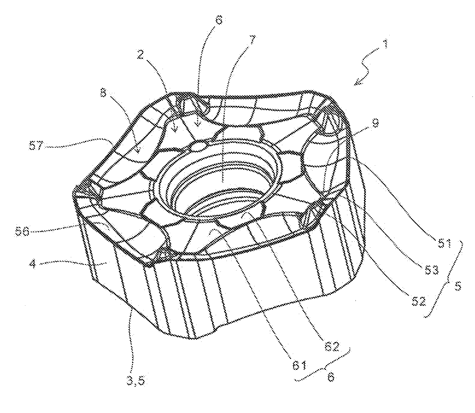
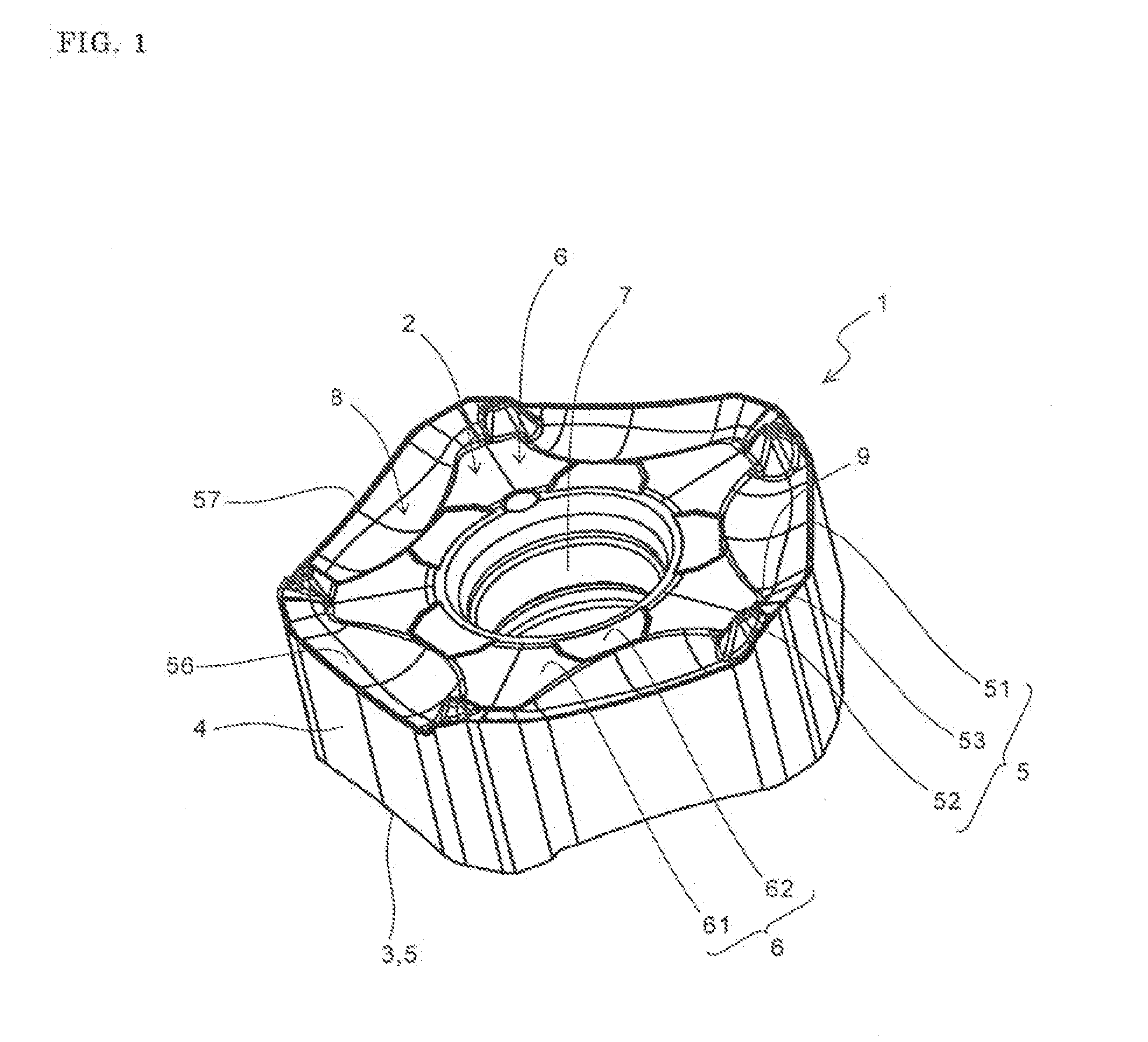
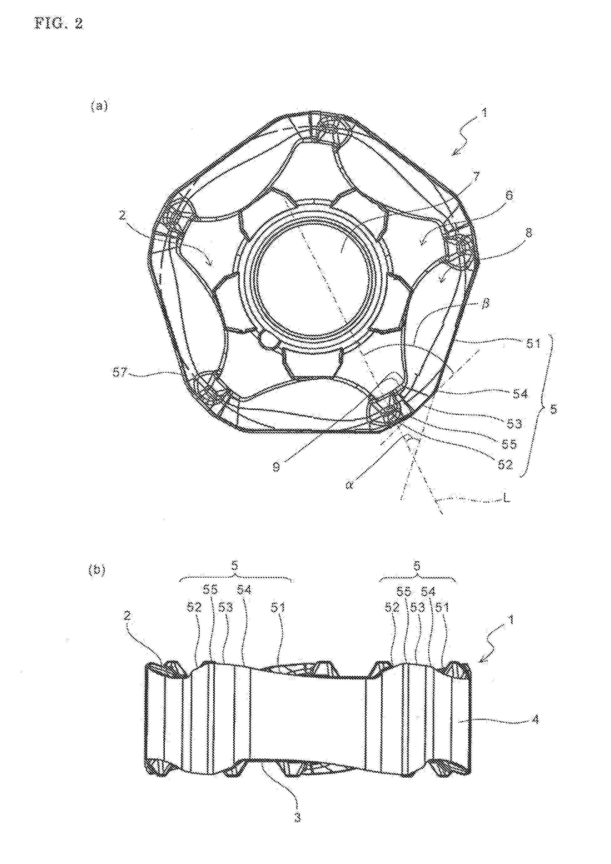
[0017]An embodiment of the cutting insert (hereinafter referred to as “insert” in some cases) according to the present invention is described in detail below with reference to FIGS. 1 to 4. Referring to FIG. 1, the insert 1 includes a body part of a substantially polygonal plate shape. No particular limitation is imposed on the shape of the body part. That is, the body part may have a certain shape usually employed by those skilled in the art, such as triangle, quadrangle, pentagon, hexagon, and octagon in a top view. The present embodiment employs a substantially pentagonal shape having five long sides. The insert size may be suitably set depending on cutting conditions. For example, the length of one side is 8-12 mm, and the thickness is 4-8 mm.

[0018]The body part also includes an upper surface 2, a part of which functions as a rake face; a lower surface 3, a part of which functions as a seating face; and a side surface 4 which is continuous with the upper surface 2 ...


PUM

PropertyMeasurementUnit
cutting edge angleaaaaaaaaaa
thicknessaaaaaaaaaa
thicknessaaaaaaaaaa

Abstract

A cutting insert of the present invention includes an upper surface; a lower surface; a side surface connected to the upper surface and the lower surface; and a cutting edge which is located along an intersection of the upper surface and the side surface, and includes a major cutting edge, a flat cutting edge, and a minor cutting edge located between the major cutting edge and the flat cutting edge. The upper surface includes a flat part located away from the cutting edge and being perpendicular to a central axis of the cutting insert, and a rake face inclined downward from the cutting edge to the flat part. In at least a part between the major cutting edge and the flat part, a groove part lies along the major cutting edge. The groove part includes the rake face and a rising face which is inclined upward from the rake face to the flat part and connects the rake face and the flat part. A connection part where the rake face and the flat part exist continuously extends from the minor cutting edge to a boundary of the minor cutting edge and the major cutting edge. A cutting tool including the cutting insert, and a method of manufacturing a machined product using the cutting tool are also provided.

Description

TECHNICAL FIELD[0001]The present invention relates to a cutting insert, a cutting tool, and a method of manufacturing a machined product using the same.BACKGROUND ART[0002]Conventionally, in a cutting insert including a major cutting edge for cutting a workpiece and a flat cutting edge for smoothing the surface of the workpiece produced by the cutting, a minor cutting edge having a larger peripheral cutting edge angle than the major cutting edge is formed between the major cutting edge and the flat cutting edge from the viewpoint of damage reduction of a cutting edge. For example, Japanese Unexamined Patent Publication No. 2008-544872 discloses a cutting insert in which the angle formed between a major cutting edge and a flat cutting edge is 45°, and an intermediate cutting edge 11 (minor cutting edge) having a larger peripheral cutting edge angle than the major cutting edge is formed between the major cutting edge and the flat cutting edge.[0003]However, in the cutting insert inclu...

Claims


Application Information

Patent Timeline
Patent Type & Authority Applications(United States)
IPC IPC(8): B23P15/28B23P13/00
CPCB23C5/06B23C5/202B23C2200/0444B23C2200/081B23C2200/087B23C2200/203Y10T407/1924B23C2200/208Y10T407/245Y10T407/235Y10T407/23Y10T29/49995B23C2200/205B23C2200/326
Inventor ISHI, HIROHISA
Owner KYOCERA CORP
Learn More