Turbomachine and impeller

Inactive Publication Date: 2012-04-19
AKER SUBSEA AS
View PDF6 Cites 5 Cited by
  • Summary
  • Abstract
  • Description
  • Claims
  • Application Information

AI Technical Summary

Benefits of technology

[0011]The turbomachine preferably includes several impellers, preferably also of the further or different types and with appropriate diffusers or similar arranged between stages or impellers in order to convert the kinetic energy into pressure. The diffusers or similar means can be a part of the casing or housing or be arranged on the shaft between stages or impellers, in the form of diffusers, stators, rectifiers, adjusters or volute chambers or other means known per se. The shaft can be divided into several releasable and thereby replaceable sections preferably coaxially connected. The casing can be divided into several parts, also inner and outer parts. The means for rotation is for example a motor of any appropriate type. The concept of having axial impellers arranged upstream of the mixed flow impeller and radial impellers arranged downstream of the mixed flow impeller has to do with the tolerance for handling gas and the capability to deliver high pressures and high throughput reliably. More specifically, the axial impellers can tolerate more gas, but deliver less pressure while the radial impellers can tolerate less gas but deliver higher pressure, relative to the mixed flow type impeller. Accordingly, high tolerance for gas can be achieved and high pressure can be achieved, since the gas can be successively compressed and the gas volume fraction can be successively reduced to a level that can be handled effectively by the next stage or impeller.
[0014]Preferably at least some impeller blades are perforated, and for impellers having several blades or pressurized volumes between blades, the perforations are not coaxial as seen parallel to the shaft. Preferably impeller blades are perforated for a number of blades, said perforations are not coaxial as seen along a circle crossing the blades, said circle being coaxial and perpendicular to the axis of rotation. Said non-coaxial arrangements will improve the remixing of gas with liquid since successive pockets of gas between blades can be avoided by arranging perforations in order to eliminate “neighbour” gas pockets. Further, at least some impellers have blades preferably having a clearance in between the blades at the portion close to the shaft, as seen parallel to the shaft, preferably said clearance, as seen along a line parallel to the shaft, in substance has the shape of a triangle having a small apex angle, and it represents a leakage passageway for fluid to remix gas and liquid.

Problems solved by technology

Apart from severe problems caused by possible contents of sand in the mixture, the gas contents impose problems for the turbomachine, as the efficiency tends to be severely reduced with increased gas volume fraction (GVF) in the mixture.

Method used


Image

  • Turbomachine and impeller
  • Turbomachine and impeller
  • Turbomachine and impeller

Examples


Embodiment Construction

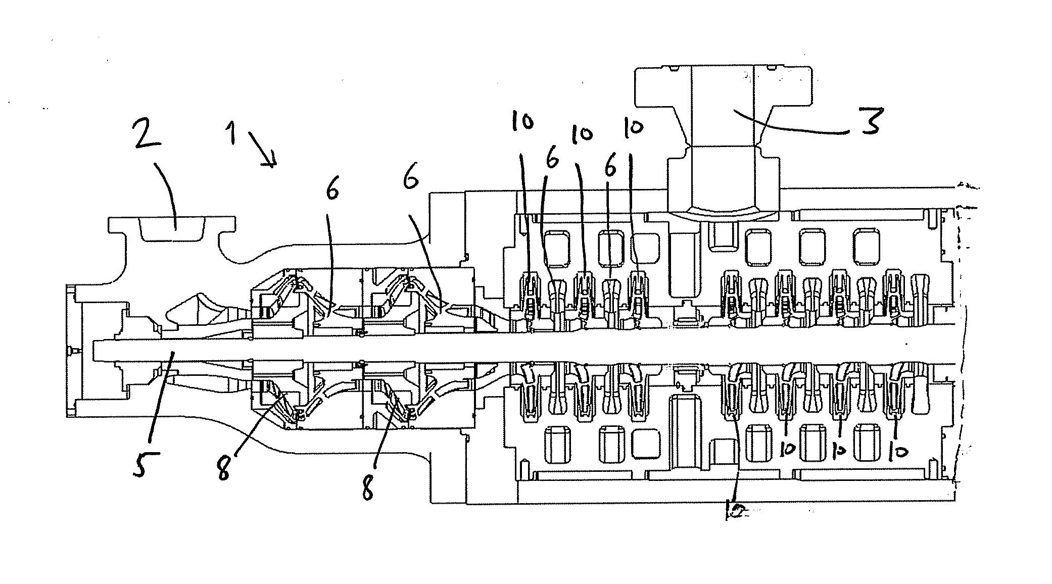
[0027]Reference is made to FIG. 1 illustrating an embodiment of a turbomachine 1 according to the present invention. More specifically the turbomachine 1 comprises an inlet 2 and an outlet 3, a casing 4 and a rotatable shaft 5 arranged in the casing, diffusers 6 or similar operatively arranged in the turbomachine, and a means 7 for rotation operatively connected to the shaft. The illustrated turbomachine comprises three impellers 8 of a mixed flow type arranged on the shaft, the impeller having an inlet and an outlet, the inlet is closer to an axis of rotation than the outlet; three axial impellers 9 arranged upstream of the mixed flow type impeller and three radial impellers10 arranged downstream of the mixed flow type impeller.

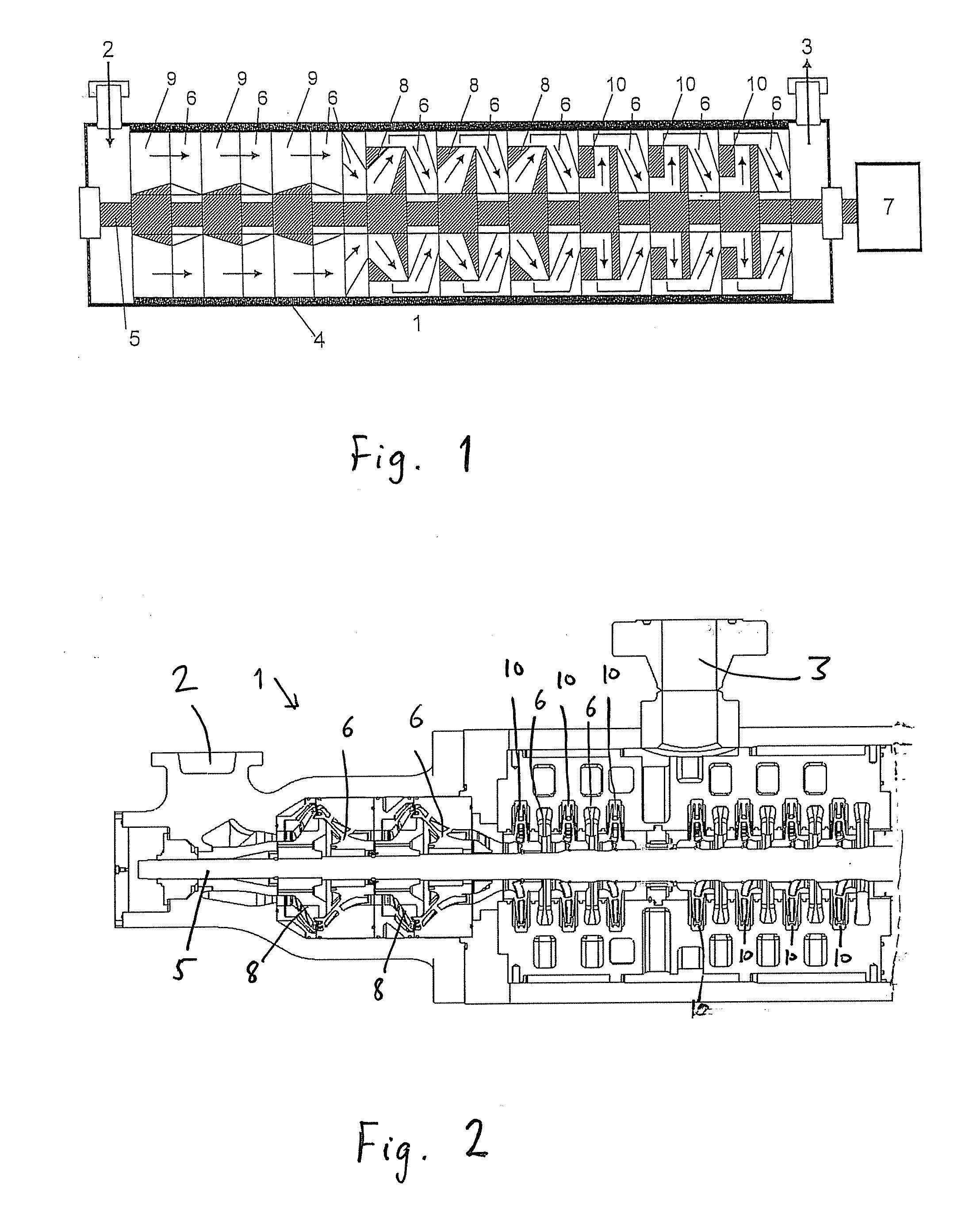
[0028]Reference is made to FIG. 2 illustrating a further turbomachine 1 of the present invention, more specifically a longitudinal section thereof. The same reference numericals as used in FIG. 1 are used for identical or similar features also in FIG. 2. The...


PUM


Abstract

Turbomachine for increasing the pressure of a fluid or mixture of fluids, comprising an inlet and an outlet, a casing, a rotatable shaft arranged in the casing, diffusers or similar operatively arranged in the turbomachine, and a means for rotation operatively connected to the shaft. The turbomachine is distinguished in that it comprises: at least one impeller of a mixed flow type arranged on the shaft, the impeller having an inlet and an outlet, the inlet is closer to an axis of rotation than the outlet; and at least one further impeller arranged on a common or operatively connected shaft, chosen from the group consisting of axial impellers arranged upstream of the mixed flow type impeller and radial impellers arranged downstream of the mixed flow type impeller. Impeller for use in a turbomachine for increasing the pressure of a fluid or mixture of fluids, the impeller comprising at least one blade, distinguished in that it comprises at least one fluid passageway fluidly connecting the pressure side of the blade with the leeward side of the blade.

Description

FIELD OF THE INVENTION[0001]The present invention relates to equipment for increasing the pressure of a fluid or a mixture of fluids, such as a mixture of oil, water and gas. More specifically, the invention relates to a turbomachine for increasing the pressure of a fluid or mixture of fluids and an impeller for use in a turbomachine.BACKGROUND OF THE INVENTION AND PRIOR ART[0002]A turbomachine is a machine that transfers energy between a rotor and a fluid, the energy is added as kinetic energy to the fluid or retrieved as kinetic energy from the fluid. Turbomachinery is a large group of machinery of which flow-machines is one type. For flowmachines having rotors, such as centrifugal pumps and compressors, the added kinetic energy is associated with an increased static pressure as the kinetic energy of the fluid is converted in means used for such purpose, such as a diffuser, a volute section or similar means. The rotors of flowmachines are usually the blades of one or more impeller...

Claims


Application Information

Patent Timeline
IPC IPC(8): F04D29/44
CPCF04D1/025F04D31/00F04D29/2288F04D13/12F04D29/2222
Inventor HOMSTVEDT, GUNDERWESTBERG, TOMMYOLDERHEIM, TARJE
Owner AKER SUBSEA AS
Why Eureka
Try Eureka