
Fan wheel for a blower module

Inactive Publication Date: 2012-04-19
ROBERT BOSCH GMBH
View PDF5 Cites 13 Cited by
  • Summary
  • Abstract
  • Description
  • Claims
  • Application Information

AI Technical Summary

Benefits of technology

[0005]It is an object of the invention to design a fan wheel and / or the balancing weights so as to ensure permanent and externally easily accessible fastening of the balancing weights and, at the same time, good balancing quality.
[0006]According to the invention, it is proposed to arrange the balancing weights at the end of the radially oriented fan blades. The balancing weight or weights is / are thus positioned at the maximum fan diameter, and therefore the balancing weight is relatively distant from the axis of rotation, or center axis, of the fan wheel. It is thus possible to select a lower weight for the balancing elements. This positioning also makes it possible for the region in which the balancing weights have to be fitted for balancing purposes still to be very easily accessible even once the fan has been installed. Handling for the operator is more straightforward and the risk of the balancing weight accidentally passing into the blower module during installation, and causing malfunctioning as a result, is lower.
[0008]The (balancing) clips differ in size, in order for it to be possible to provide the operator with a selection of different balancing masses. It is also possible to use different shapes. On the one hand, the (balancing) clip is adapted to the shape of the fan blade and, on the other hand, the attempt is made, by configuring the (balancing) clips in a suitable manner, to improve the form fitting or frictional fitting.
[0009]The inside and outside of the radially oriented fan blades contain grooves, in which the (balancing) clips engage in a form-fitting manner by way of their clamping edges. As a result of these grooves, it is advantageously the case that the (balancing) clips are secured against being slung off axially not only by frictional fitting, but also by corresponding form fitting. Furthermore, the grooves ensure always the same axial positioning of the (balancing) clips, which helps to achieve a uniform quality for the balancing of moments, since the balancing plane is clearly defined.
[0010]The radially oriented fan blades form a fan ring, which is made up alternately of short and long fan blades, wherein the (balancing) clips and the grooves for the (balancing) clips are provided at the radial end of the fan blades. The balancing clips are arranged preferably on the long fan blades, since these are designed to be stiffer than the short fan blades and are thus less likely to vibrate.
[0011]The fan wheel is produced preferably by injection molding, wherein the grooves can advantageously be demolded from the mold without any additional outlay.

Problems solved by technology

Handling for the operator is more straightforward and the risk of the balancing weight accidentally passing into the blower module during installation, and causing malfunctioning as a result, is lower.

Method used


Image

  • Fan wheel for a blower module
  • Fan wheel for a blower module
  • Fan wheel for a blower module

Examples


Embodiment Construction

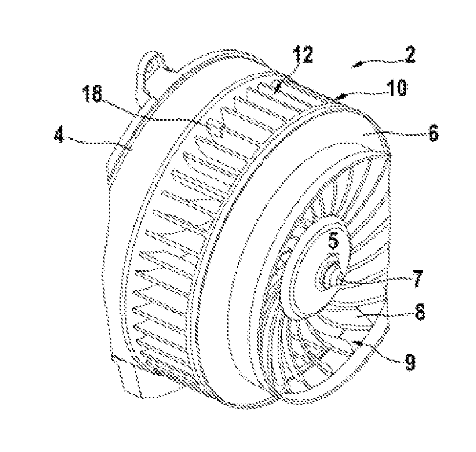
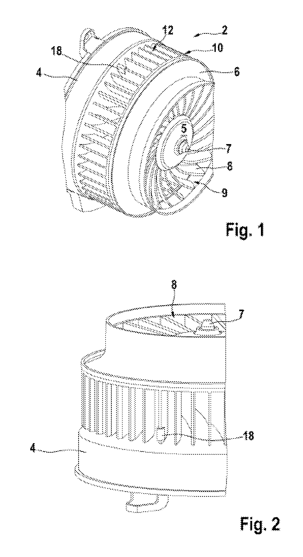
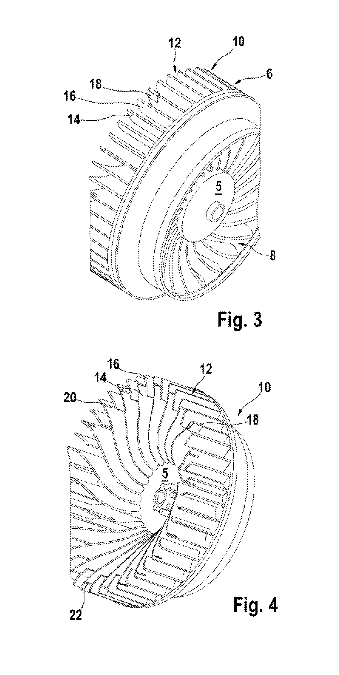
[0020]The blower module 2 illustrated in FIG. 1 comprises a basic housing 4, on which a fan wheel 6 is mounted such that it can be rotated on a drive shaft 7. The fan wheel 6, in turn, is fastened on the drive shaft 7 by way of its hub 5. The (radial) fan wheel 6 has, on its outer end side, an axial fan ring 8, which is made up of curved fan blades 9. The (radial) fan wheel 6 also has a radial fan ring 10, which is likewise made up of curved fan blades, referred to hereinbelow as radial fan blades 12. As can be seen from FIG. 4, the radial fan ring 10 has two different types of fan blade 12. A first group comprises long fan blades which extend as far as the hub 5, and will be referred to hereinbelow as long fan blades 14, whereas a second group comprises short fan blades 16 which, as seen from the external diameter of the radial fan ring 10, extend only some way in the direction of the axis of rotation. The two groups of fan blades 14, 16 are formed alternately on the (radial) fan w...


PUM


Abstract

The invention relates to a fan wheel (6) for a blower module (2), comprising a hub (5) and a radial fan ring (8) composed of a plurality of fan blades (12) and further comprising means for resolving imbalances in the fan wheel (6). According to the invention, balancing weights (18) can be fastened to the radial ends of the fan blades (12).

Description

BACKGROUND OF THE INVENTION[0001]The present invention proceeds from a fan wheel for a blower module.[0002]Such blower modules are known from a wide variety of different industrial applications, for example they are used for ventilating various technical appliances or for channeling the air stream when used in air-conditioning systems of motor vehicles.[0003]In many applications, for example when used in air-conditioning systems of motor vehicles, the fans of the blower modules are balanced following installation. Usually, added or positive balancing is carried out here with balancing weights, e.g. in the form of (balancing) clips, being fitted on the fan wheel. The balancing weights here are fixed in the selected position by resilience and frictional fitting. The balancing weights are usually fastened exclusively on the (axial) inside of the fan blades, this side being directed toward the fan center point, and they are secured here by form fitting against the radially acting centri...

Claims


Application Information

Patent Timeline
IPC IPC(8): F01D25/04
CPCF04D29/662F04D29/281F04D29/28F04D29/66
Inventor HUBER, MARTINPRAHL, DETLEF
Owner ROBERT BOSCH GMBH
Learn More