Compact pedal system for a motor vehicle

a pedal system and motor vehicle technology, applied in the direction of mechanical control devices, limiting/preventing/returning movement of parts, controlling members, etc., can solve the problems of relatively large bending torque acting directly on the rotor shaft, changing the air gap between the stator and the rotor, and high manufacturing and calibration costs. achieve the effect of increasing the for

Inactive Publication Date: 2012-04-26
CONTI TEMIC MICROELECTRONIC GMBH
View PDF10 Cites 9 Cited by
  • Summary
  • Abstract
  • Description
  • Claims
  • Application Information

AI Technical Summary

Benefits of technology

[0019]A brushless direct current motor can be used, for example, as an electric motor. In order to be able to use a direct current motor with a small overall size and low power drain, a self-locking transmission is generally additionally used to increase the force, which has the advantage that after a predefined resetting force has been reached by the direct current motor, the latter can be placed in a de-energized state, and the resetting force is maintained by the self-locking effect of the transmission. The self-locking transmission is then advantageously arranged between the drive pulley and the rotor and is permanently connected to the shaft of the electric motor in order to transmit force. In this case, the drive pulley is mounted in a freely rotatable fashion on the shaft of the electric motor. The one end of the motor return spring acts on the drive pulley, and the other end of the motor return spring is permanently connected to the self-locking transmission. As a result, the prestress of the motor return spring can be varied, both in the direction of the zero position and in the direction of the end position of the electric motor, between a minimum value and a maximum value.

Problems solved by technology

Such a device for controlling the speed of a vehicle is composed of a multiplicity of independent components which have to be mounted and adjusted to one another with great effort.
As a result, both the manufacture and the calibration of the device are very costly.
A disadvantage of this device is that, when the resetting force is applied to the pedal lever by the rotor, a relatively large bending torque acts directly on the rotor shaft.
As a result, as a rule the air gap between the stator and rotor changes and the actuation capability of the torque motor is adversely affected.

Method used


Image

  • Compact pedal system for a motor vehicle
  • Compact pedal system for a motor vehicle
  • Compact pedal system for a motor vehicle

Examples


Embodiment Construction

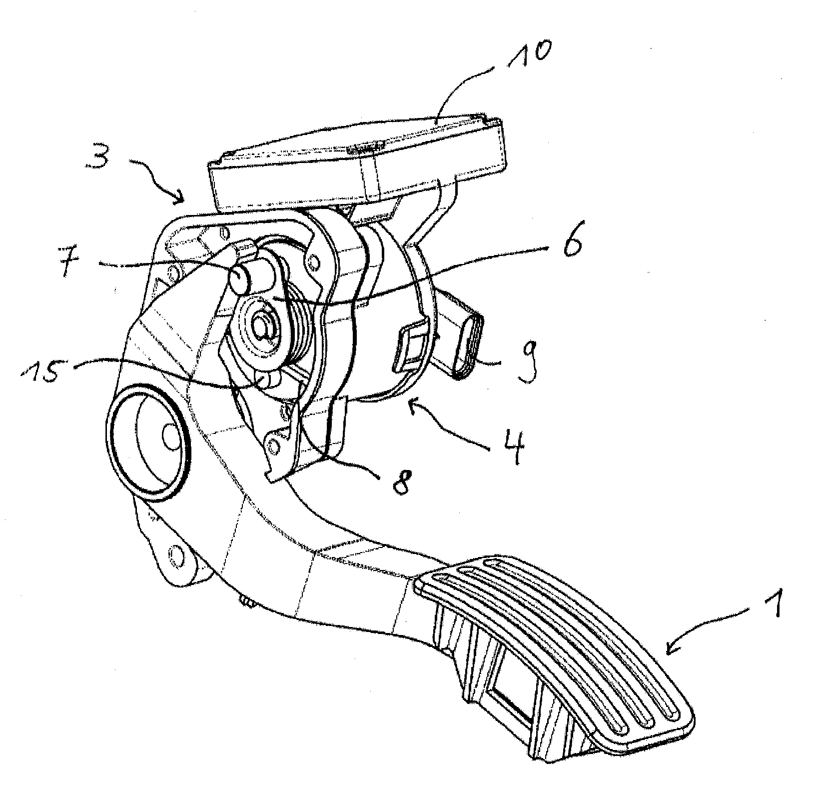
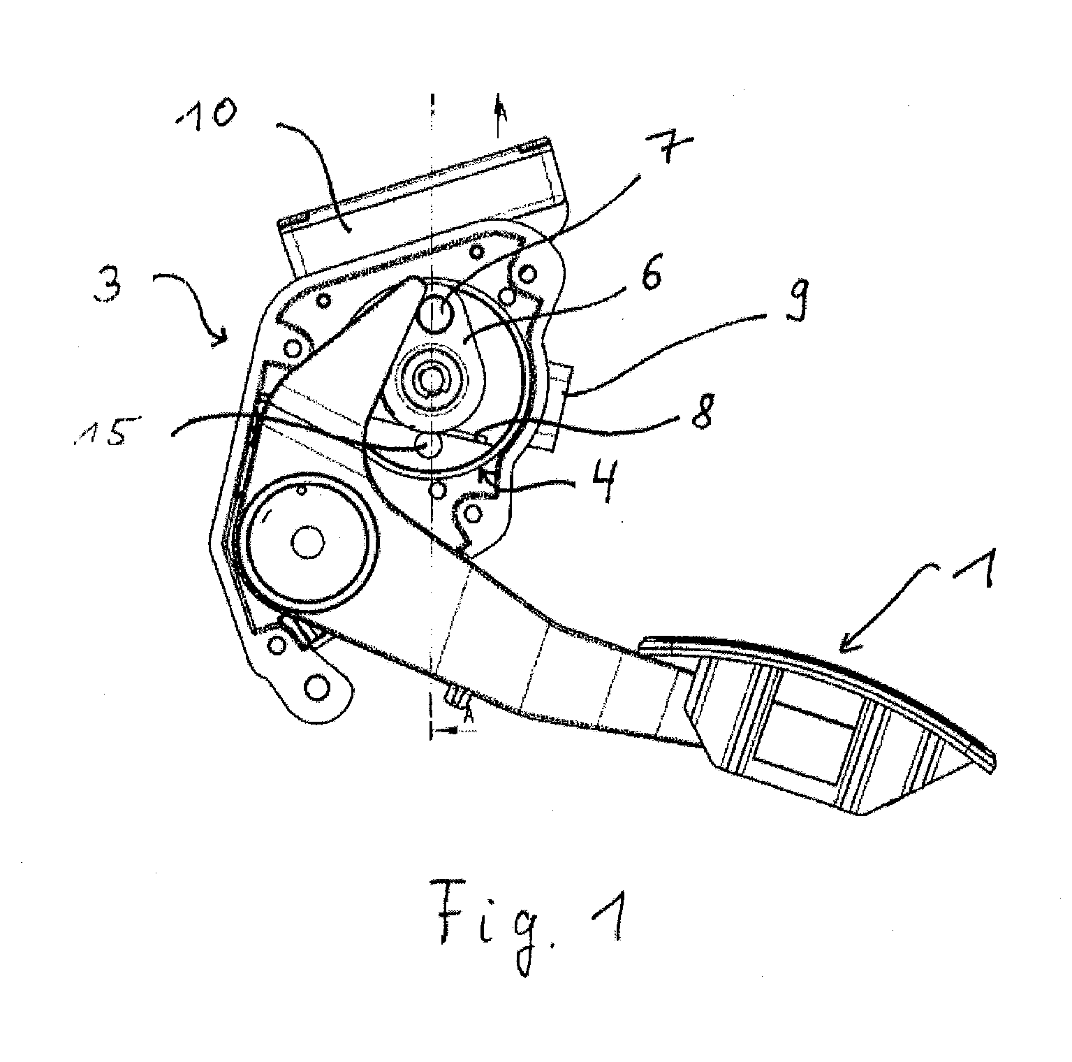
[0028]FIG. 1 shows a compact pedal system for regulating the speed, wherein a force resetting device is integrated into the housing 3. The pedal system comprises essentially a pedal lever 1 for converting the driver's request into speed. An electric motor 4, in particular a torque motor, as a further component of the force resetting device can, in the de-energized state, apply a resetting force to the pedal lever 1 in the direction of reducing the speed. At the electric motor 4, a drive pulley 6 is rotatably arranged, which drive pulley 6 can apply the resetting force to the pedal lever 1 by means of a drive roller 7 or other suitable devices such as, for example, sliding free-form faces. A control unit 10 for controlling the electric motor 4 is also integrated into the housing 3.

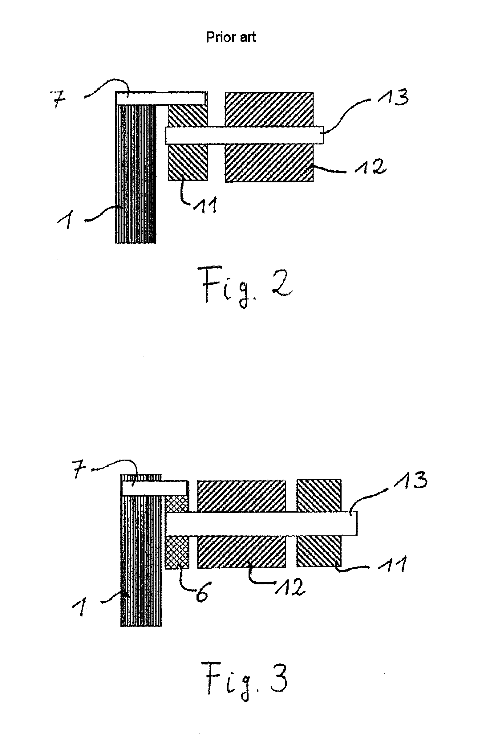
[0029]The electric motor 4 comprises essentially a stator 12 and a rotor 11 which is connected to a shaft 13 which can rotate in the stator 12. FIGS. 2 and 3 each show a basic arrangement of the components ...


PUM


Abstract

A pedal system that has a force resetting device essentially including a pedal lever with a pedal return spring that can bring the pedal lever into the neutral position (PN), an electric motor that can be swiveled about a pivot (M) and can, in the energized state, apply a resetting force (F) to the pedal lever in the direction of the neutral position (PN) of the pedal lever, a motor return spring for resetting the electric motor in the direction of the neutral position (MN) of the electric motor, and a control unit for controlling the electric motor. The electric motor includes a rotor and a stator which is arranged on the shaft of the electric motor, between the rotor and the drive disk.

Description

CROSS REFERENCE TO RELATED APPLICATIONS[0001]This application is the U.S. National Stage Application of PCT / EP2010 / 056064, filed May 5, 2010, which claims priority to German Patent Application 10 2009 021 585.9, filed May 15, 2009, the contents of such applications being incorporated by reference herein.FIELD OF THE INVENTION[0002]The invention relates to a compact pedal system for a motor vehicle according to a compact pedal system for regulating the speed in a motor vehicle, having a force resetting device which is integrated in a housing.BACKGROUND OF THE INVENTION[0003]In the automobile industry there is a trend for the driver of a vehicle to be assisted with respect to driving safety, driving comfort and driving efficiency. Examples of this are lane keeping systems or systems with a cruise controller function. In this context, the driving behavior of the motor vehicle is influenced in an assisting fashion on the basis of measured vehicle parameters and ambient parameters. The f...

Claims


Application Information

Patent Timeline
Patent Type & Authority Applications(United States)
IPC IPC(8): G05G1/44
CPCG05G1/30Y10T74/20534G05G5/03B60K31/00
Inventor LEONE, CARMELODREWS, FRANKBAUMLER, JURGENBRANDT, THOMAS
Owner CONTI TEMIC MICROELECTRONIC GMBH
Why Eureka
Try Eureka