Scanning incremental focus microscopy

a microscopy and incremental focus technology, applied in the field of objects imaging, can solve the problems of increasing the cost of microscopes with extremely small probe sizes, limiting the ability to obtain high resolution images of discernable features, and increasing the cost of reducing the probe siz

Inactive Publication Date: 2012-04-26
THE RES FOUND OF STATE UNIV OF NEW YORK
View PDF2 Cites 18 Cited by
  • Summary
  • Abstract
  • Description
  • Claims
  • Application Information

AI Technical Summary

Benefits of technology

[0005]The shortcomings of the prior art are overcome and advantages are provided through the provision of an improved method for generating an image. The method includes, for instance, obtaining images of an area of an object generated using probes equal to or greater than

Problems solved by technology

Similarly, if the signal is very weak, even when high resolution is possible and the contrast is adequate, then noise may still limit the ability to obtain high resolution images of discernable features.
However, because of the strong relationships that exist between resolution, contrast and signal to noise ratio in scanning probe techniques, reducin

Method used


Image

  • Scanning incremental focus microscopy
  • Scanning incremental focus microscopy
  • Scanning incremental focus microscopy

Examples


Embodiment Construction

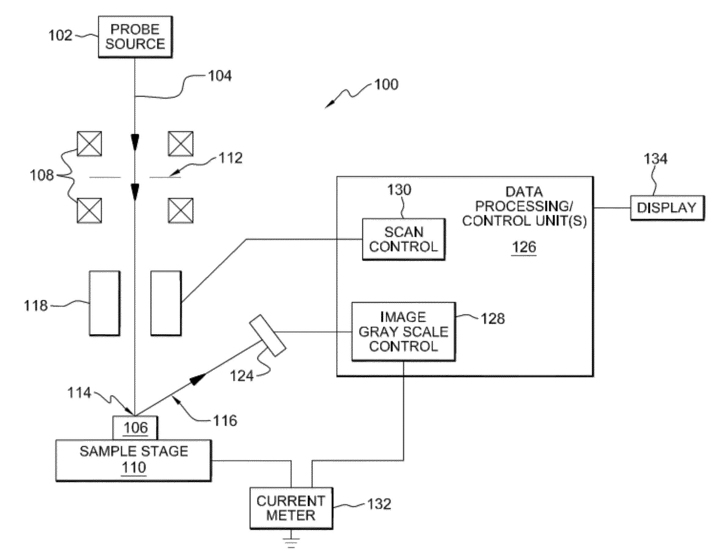
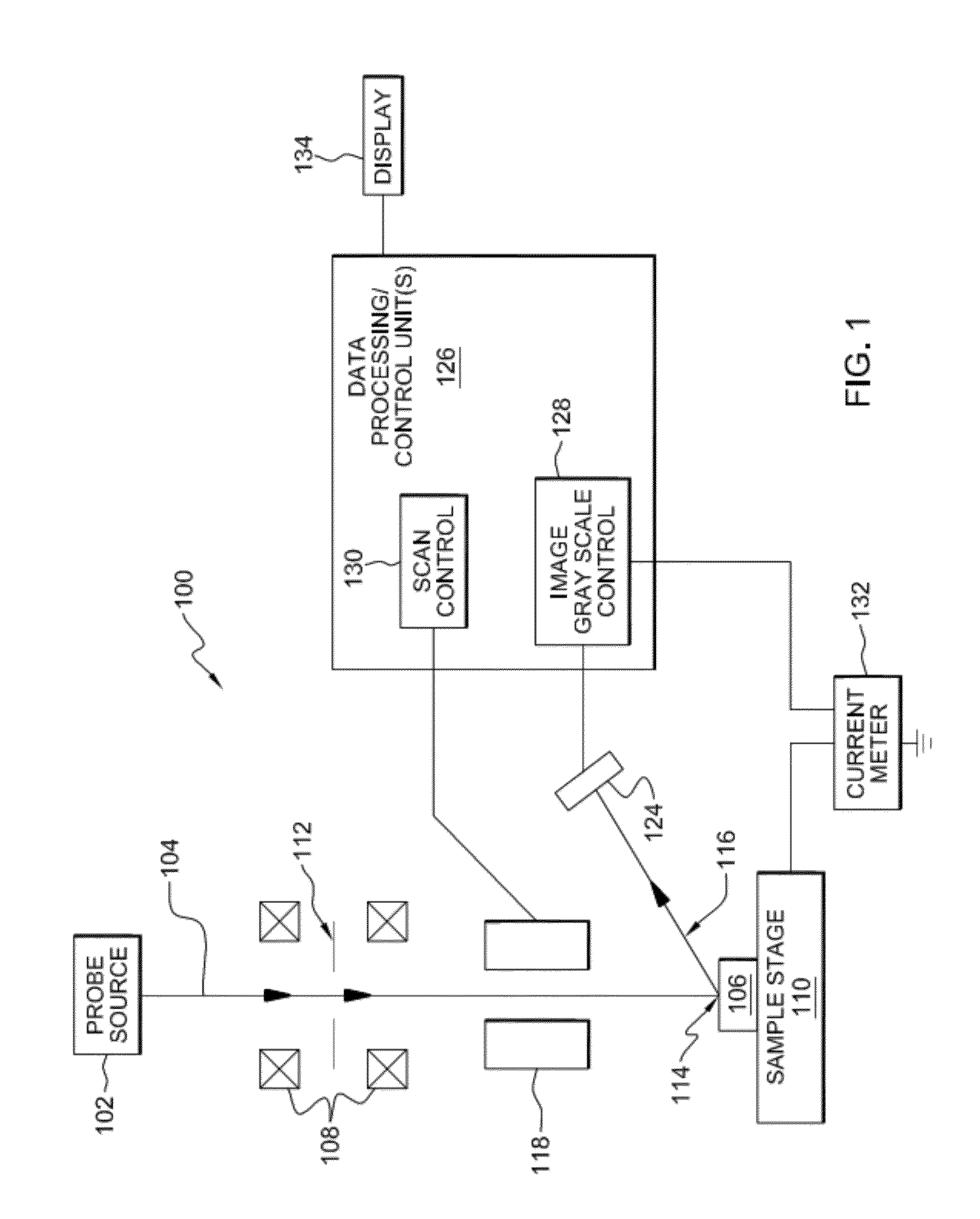
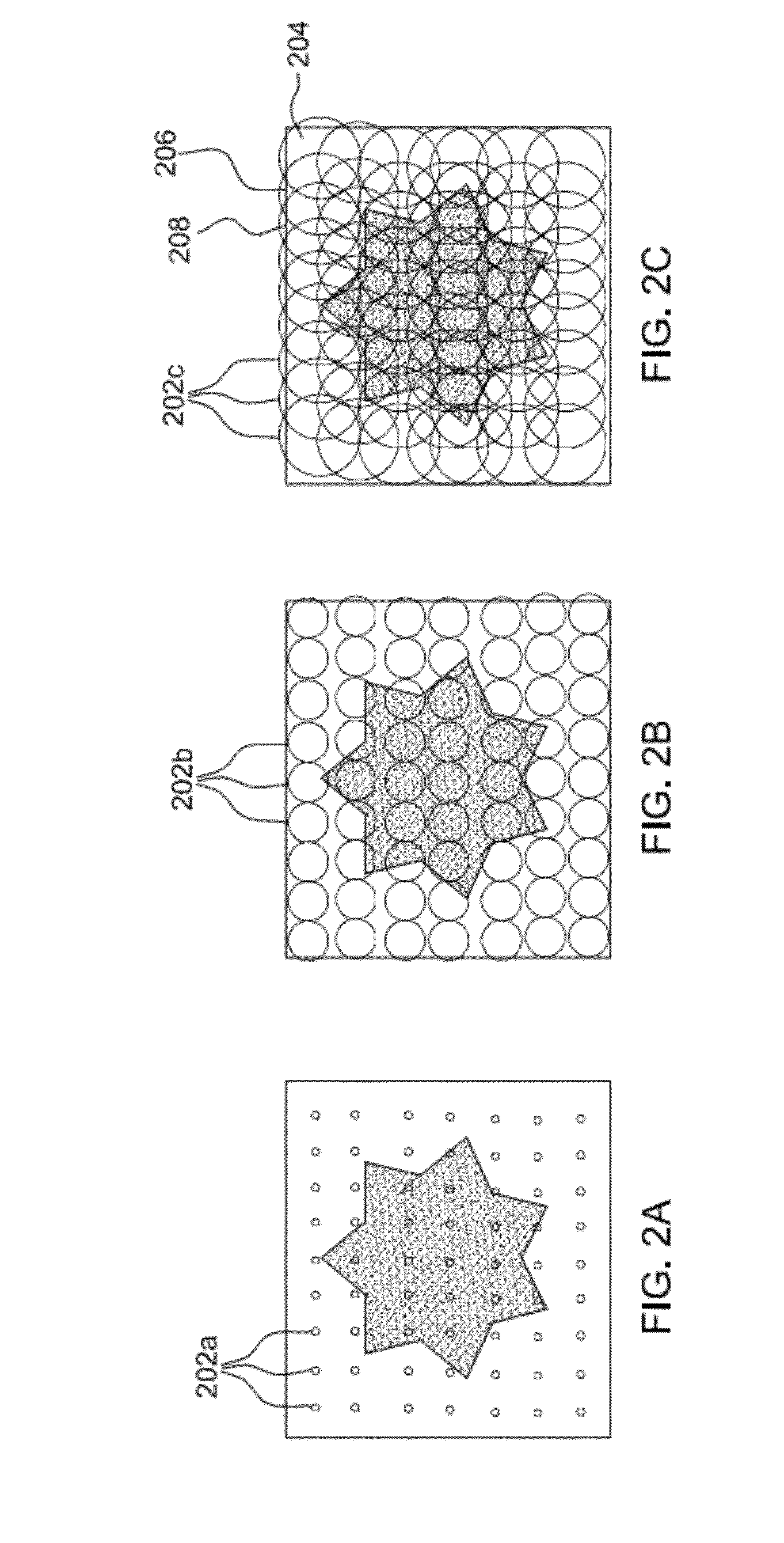
[0016]Aspects of the present invention can be used in conjunction with various imaging techniques, including sequential imaging techniques. Sequential imaging involves scanning a probe across a sample object, typically in a series of lines called a raster. At the same time, a signal related to the intensity of an emission (an ‘emission intensity’) generated by the probe, or the reflected intensity of the probe itself, striking various points of the sample object, may be displayed on a synchronously scanned display.

[0017]One example of a sequential imaging technique with which the present invention may be employed is scanning electron microscopy (SEM), where the probing signal is an electron beam and the generated signal typically (though not always) consists of secondary electrons. In SEM, electrons are directed from a source towards a sample. Sources can include a tungsten filament, a lanthanum hexaboride filament, a cold field emitter, or a Schottky emitter, to name a few. In SEM,...


PUM


Abstract

Method and apparatus are provided for generating an enhanced image of an object. The method includes obtaining images of an area of an object generated using a probe of having a probe size greater than or equal to a minimum probe area size. An enhanced image of the area of the object is generated by accurately computing the emission intensities emitted from pixel areas smaller than the minimum probe size and within the area of the object. This is repeated for other areas of the object to form other enhanced images. The enhanced images are combined to form an accurate enhanced image of the object.

Description

TECHNICAL FIELD [0001]This invention relates generally to the imaging of objects, and more specifically to techniques for generating enhanced resolution images.BACKGROUND OF THE INVENTION[0002]In microscopic imaging, efforts are continually being made to achieve higher resolution microscopic images. For example, in the case of scanning probe techniques, the quest for high resolution has traditionally been addressed by finding ways to reduce the probe size while minimizing the corresponding reduction of probe current so as not to encounter serious signal to noise limitations, since the signals measured are always directly proportional to the probe current. In scanning electron microscopy (SEM), for instance, the major ways to accomplish this has been through a combination of brighter sources, such as the use of field emission and Schottky sources, as well as improvements in electron optical design. Similar developments are taking place in other techniques such as scanning transmissio...

Claims


Application Information

Patent Timeline
IPC IPC(8): G01N23/04
CPCG02B21/002G06T3/4053H01J37/222H01J37/263G01N23/225H01J31/265H01J31/28H01J37/28
Inventor LIFSHIN, ERICSTESSIN, MICHAELCHAGOUEL, ISAAK
Owner THE RES FOUND OF STATE UNIV OF NEW YORK
Why Eureka
Try Eureka