Member mount and assembly structure thereof

a member mount and assembly technology, applied in the direction of shock absorbers, machine supports, other domestic objects, etc., can solve the problems of increasing the cost of the member mount, increasing the cost of the inner tubular member, and high processing costs

Active Publication Date: 2012-04-26
SUMITOMO RIKO CO LTD
View PDF3 Cites 22 Cited by
  • Summary
  • Abstract
  • Description
  • Claims
  • Application Information

AI Technical Summary

Benefits of technology

[0041]In addition, it is preferable in the present invention that the connection holes and the resin connection portions be each provided in the axially central portion of the inner tubular member having an axially straight shape (fourth aspect). With the connection holes and the resin connection portions positioned closer to one end from the axially central portion, the binding function by the resin connection portions on the inner peripheral resin layer is different on one end from on the other end in the axial direction, and a force to prevent deformation of the inner peripheral resin layer is relatively small on the other end in the axial direction. Providing the connection holes and the resin connection portions in the axially central portion prevents deformation of the inner peripheral resin layer equally on one end and on the other end in the axial direction.
[0042]In contrast, the outer peripheral resin layer may be provided closer to one end in the axial direction of the inner tubular member having an axially straight shape (fifth aspect). Thus, th

Problems solved by technology

Furthermore, the processing cost is high due to individual forging and forming of the inner tubular member 208, increasing the cost of the member mount 204.
Preparing the inner tubular

Method used


Image

  • Member mount and assembly structure thereof
  • Member mount and assembly structure thereof
  • Member mount and assembly structure thereof

Examples


Embodiment Construction

[0055]The particulars shown herein are by way of example and for purposes of illustrative discussion of the embodiments of the present invention only and are presented in the cause of providing what is believed to be the most useful and readily understood description of the principles and conceptual aspects of the present invention. In this regard, no attempt is made to show structural details of the present invention in more detail than is necessary for the fundamental understanding of the present invention, the description is taken with the drawings making apparent to those skilled in the art how the forms of the present invention may be embodied in practice.

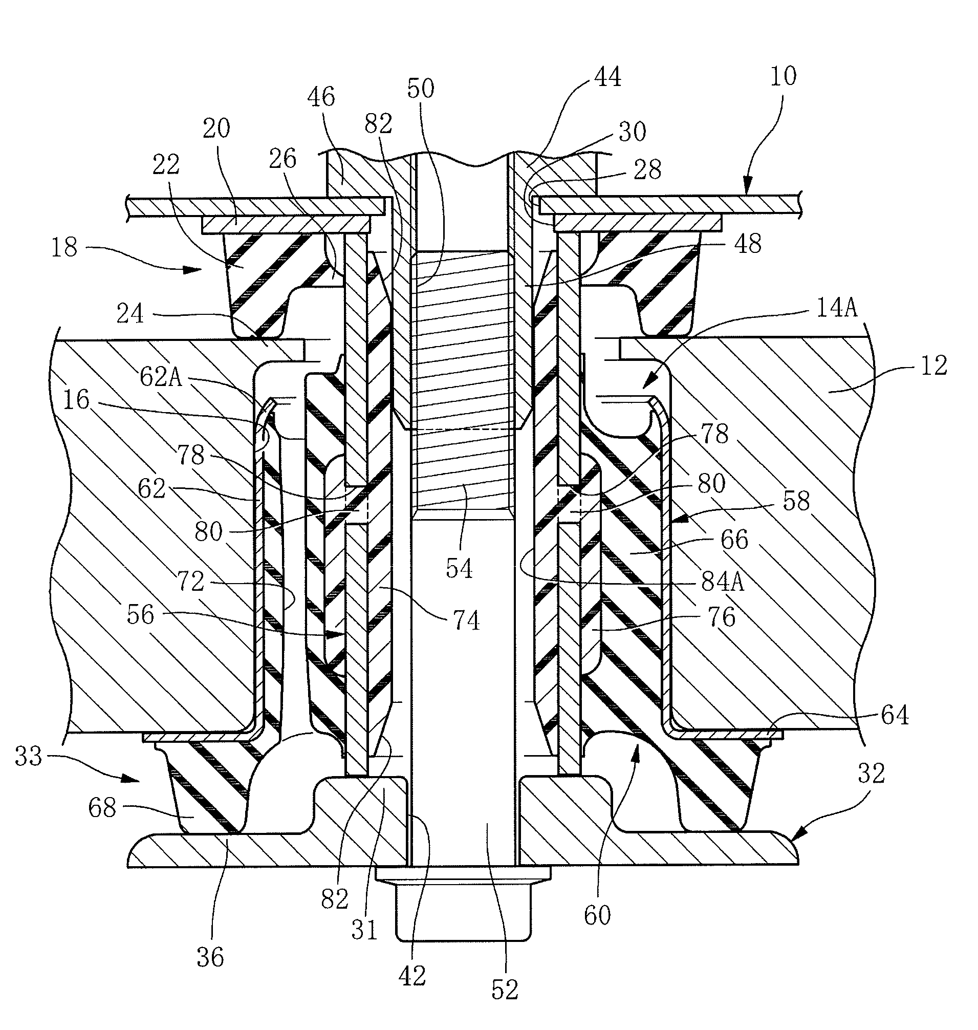
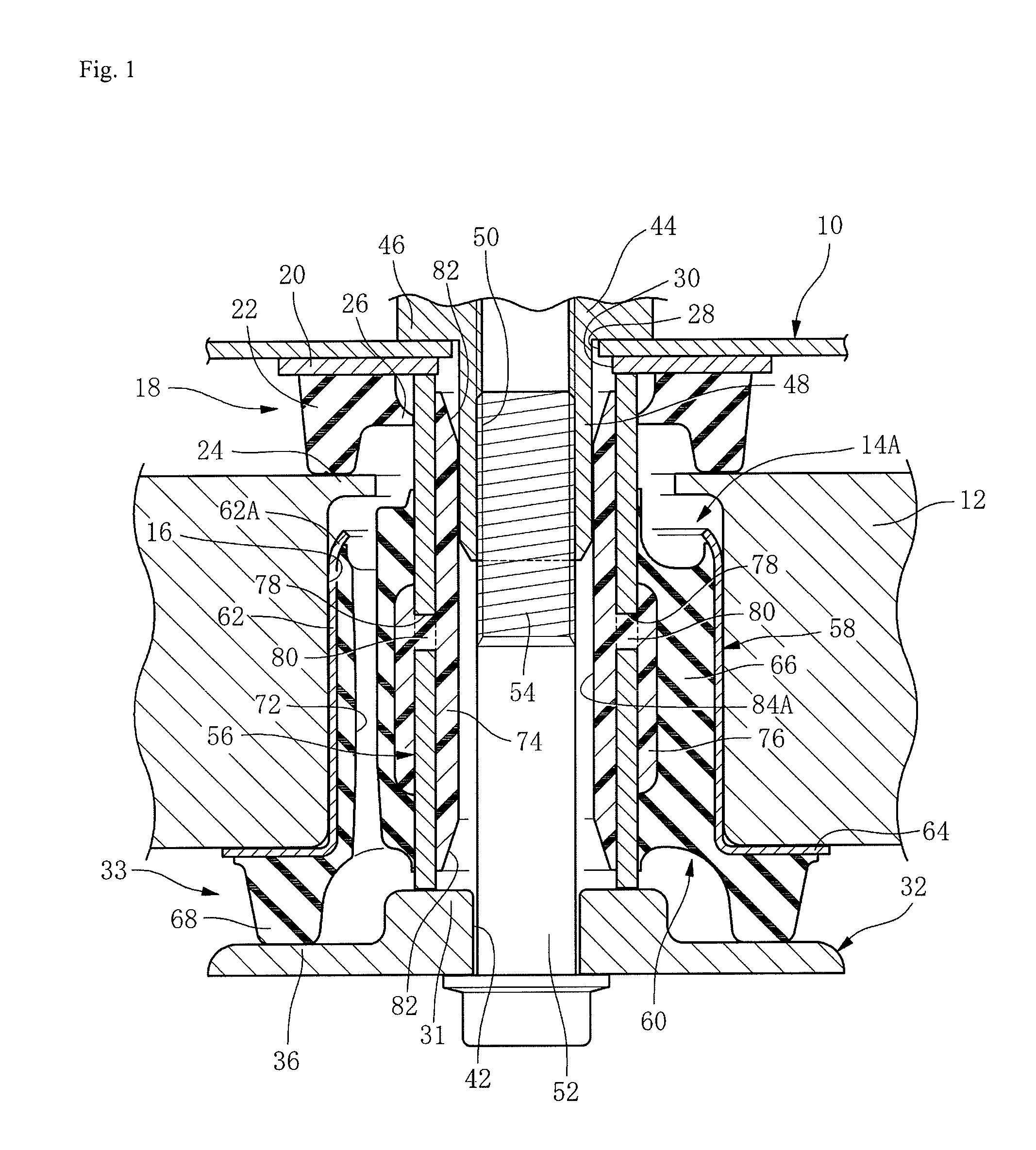
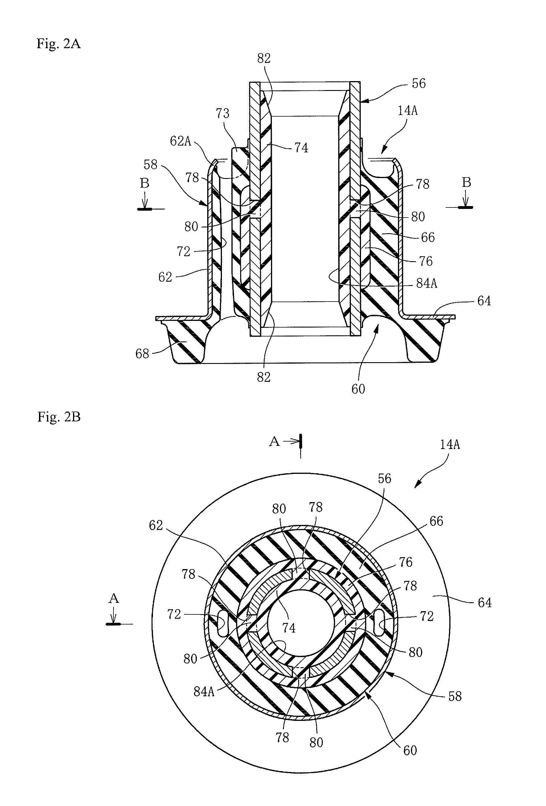
[0056]The embodiments of the present invention are explained in detail below with reference to the drawings. FIG. 1 includes a panel-shaped vehicle body member 10, a sub-frame 12 (octothorpe (hash-character)-shaped sub-frame) as a suspension member, and a member mount 14A elastically connecting the sub-frame 12 and the and the...


PUM


Abstract

A member mount has an inner tubular member, an outer tubular member, and a rubber elastic body connecting the tubular members. An inner peripheral resin layer having an inner hole as a positional hole is layered on an internal peripheral surface of the inner tubular member and an outer peripheral resin layer is layered on an outer peripheral surface thereof. The resin layers are connected to each other in resin connection portions in connection holes passing through the inner tubular member in four positions in the circumferential direction at equal distances.

Description

CROSS-REFERENCE TO RELATED APPLICATIONS [0001]The present application claims priority under 35 U.S.C. §119 of Japanese Applications No. 2010-239493, filed on Oct. 26, 2010, and No. 2011-230194, filed on Oct. 19, 2011, which are herein expressly incorporated by reference in their entireties.BACKGROUND OF THE INVENTION[0002]1. Field of the Invention[0003]The present invention relates to a member mount elastically connecting a suspension member and a vehicle body of an automobile and isolating vibration therebetween, and an assembly structure of the member mount.[0004]2. Description of Related Art[0005]A suspension member, such as a sub-frame, is a skeletal frame member of a part of a vehicle to mount a suspension. The suspension is assembled to a vehicle body through the suspension member. In general, the suspension member and the vehicle body are elastically connected by a member mount. The member mount maintains a proper relative positional relationship between the suspension member...

Claims


Application Information

Patent Timeline
IPC IPC(8): F16F7/00
CPCF16F1/3863F16F1/3842
Inventor YAHATA, YUKI
Owner SUMITOMO RIKO CO LTD
Why Eureka
Try Eureka