Apparatus for detecting the position of a rotor of an electric motor and related method

a technology of electric motor and rotor, which is applied in the direction of synchronous motor starters, electronic commutators, starter arrangements, etc., can solve the problems of loss of synchronism, reduced efficiency, and inability to accurately estimate the position of the rotor, so as to ensure the accuracy of the estimation of the rotor position

Inactive Publication Date: 2012-04-26
STMICROELECTRONICS SRL
View PDF5 Cites 9 Cited by
  • Summary
  • Abstract
  • Description
  • Claims
  • Application Information

AI Technical Summary

Benefits of technology

[0013]One embodiment of the present disclosure is an apparatus for detecting the position of a rotor of an electric motor, in particular a brushless motor, which overcomes the drawbacks of known apparatuses. With the apparatus in accordance with the disclosure, the problem of the position error generated by BEMF is minimized, thus ensuring the precision of the estimation of the rotor position for higher rotation speeds with respect to this which may be obtained, by using the known art inductive sense methods.

Problems solved by technology

Indeed an error in detecting the rotor position results in an imprecise excitation sequence of the stator phases and in a consequent efficiency reduction or, in the worst case, in a failure of the motor startup procedure (loss of synchronism).
In these cases the result is affected by the errors made in the individual measurements, since it is based on the comparison of various measurements made in sequence.
The typical problem of an inductive sense procedure is that of the precision in the case wherein the motor moves, i.e., when the back electromotive force (BEMF) is not null or at least negligible.
Under these conditions, the current pulses are modified by the presence of BEMF, thus generating an error when detecting the rotor position.
Therefore, in the known art systems, a maximum limit of BEMF (and therefore of speed) exists, which may not be overcome if the desired precision and reliability in detecting the position of the rotor is to be ensured.

Method used


Image

  • Apparatus for detecting the position of a rotor of an electric motor and related method
  • Apparatus for detecting the position of a rotor of an electric motor and related method
  • Apparatus for detecting the position of a rotor of an electric motor and related method

Examples


Embodiment Construction

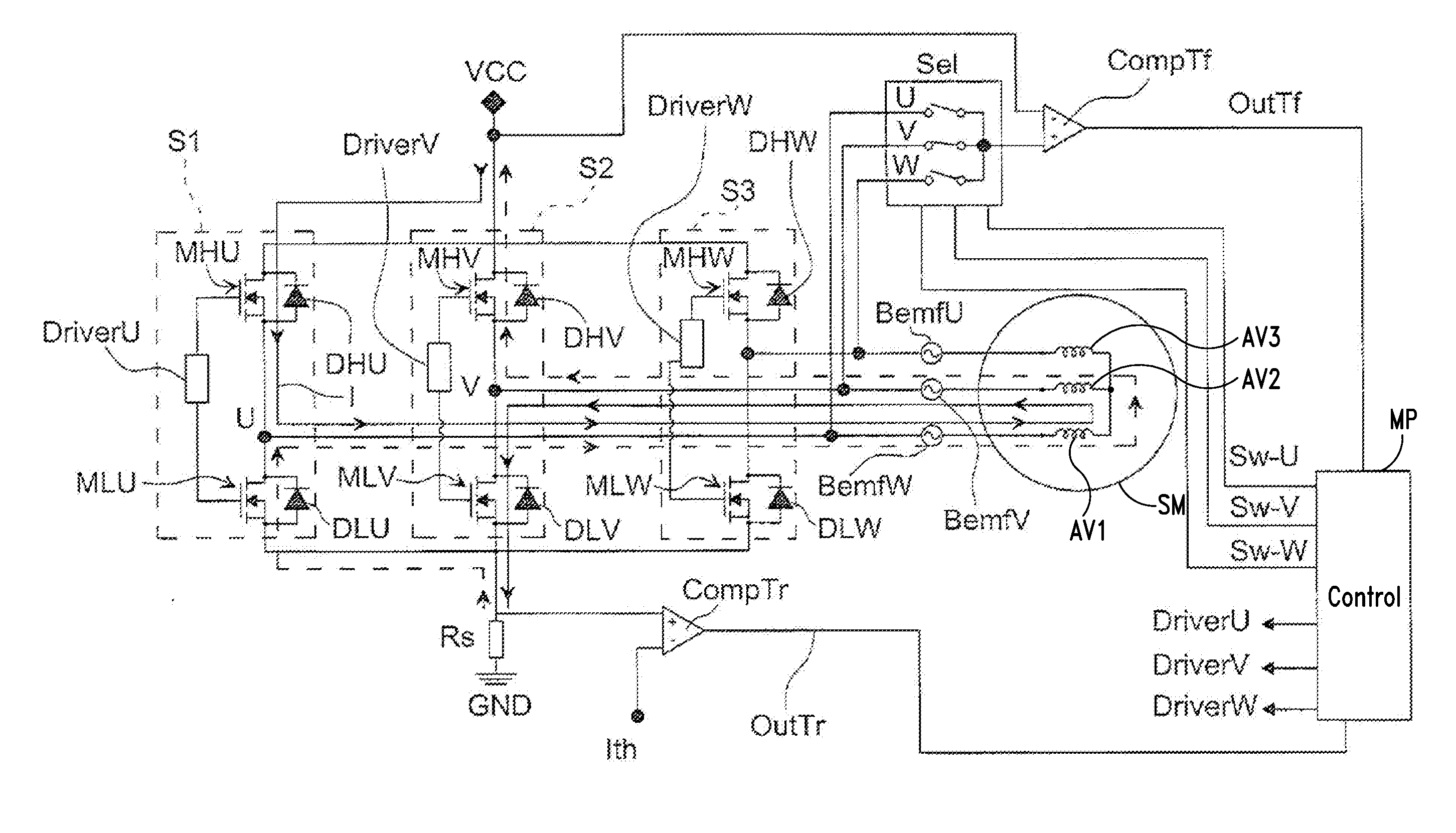
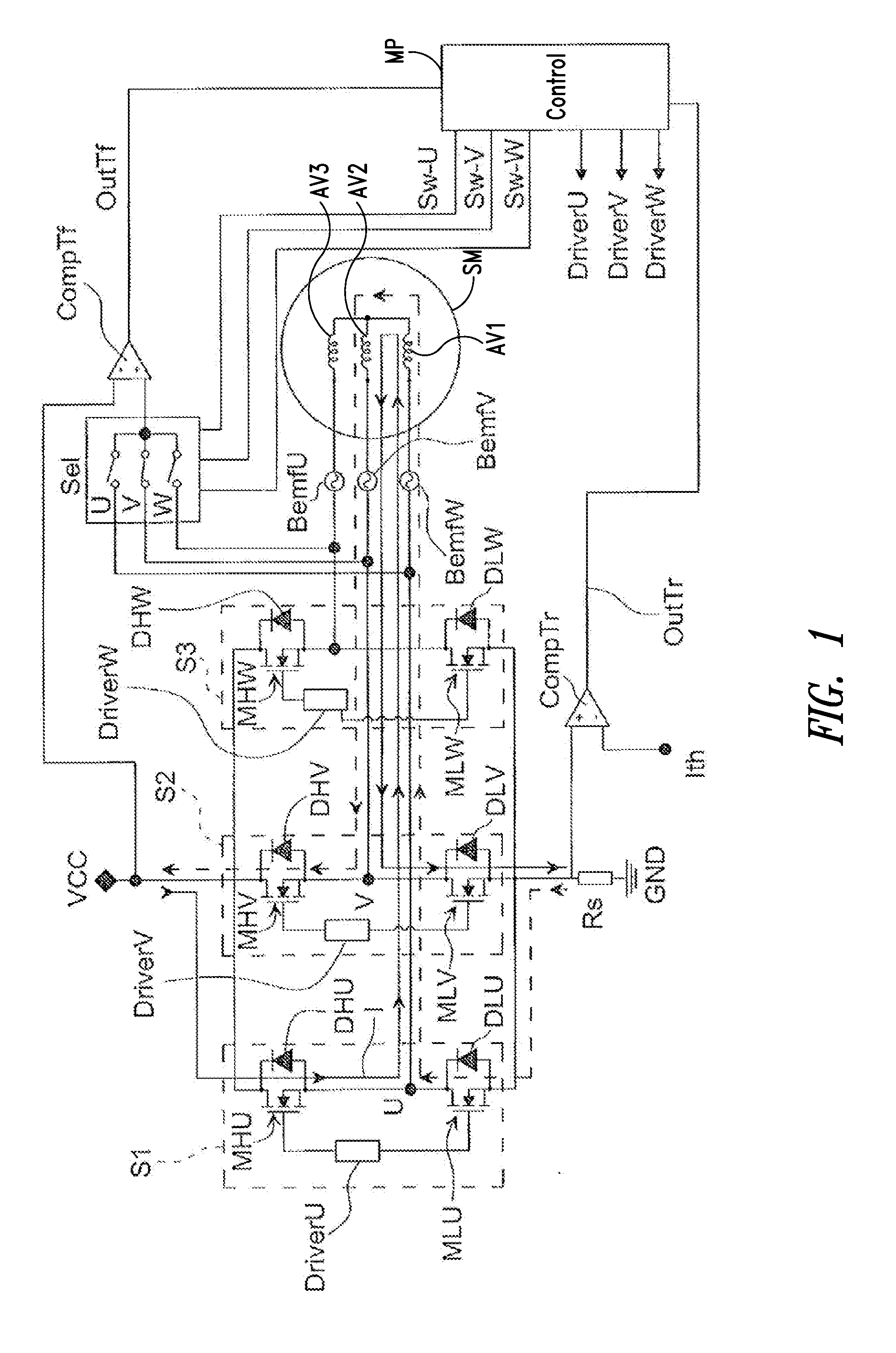
[0028]FIG. 1 shows an apparatus for detecting the position of a rotor of an electric motor, in particular a brushless motor SM, according to an embodiment of the present disclosure; the electric motor is of the N-phase type, preferably having three phases. The apparatus comprises the half-bridges S1, S2 and S3 for controlling the brushless motor SM comprising a rotor; FIG. 1 shows the stator of the electric motor SM with the three star-connected phases U, V and W which include windings AV1, AV2, and AV3, respectively. Each of the half-bridges consists of a “high side” transistor and a low side transistor, each with the associated recirculating diode, indicated respectively by MHU, MLU and DHU, DLU for the half-bridge S1, and MHV, MLV and DHV, DLV for the half-bridge S2 and MHW, MLW and DHW, DLW for the half-bridge S3. The high-side transistors have their drain terminal connected to the positive power supply voltage terminal VCC while the low-side transistors have the source terminal...


PUM


Abstract

An apparatus detects the position of a rotor of an electric motor having three phases and a plurality of windings. The apparatus includes circuitry configured to connect at least two of said windings between first and second reference voltages according to a first current path disconnect said at least two windings, and allow the current stored in said two windings to be discharged through a second current path. The apparatus comprises a measuring circuit configured to measure the time period between the starting instant of storing the current in the two windings and the final instant of discharging the two windings and a rotor detector configured to detect the rotor position based at least in part on the measured time period.

Description

BACKGROUND[0001]1. Technical Field[0002]The present disclosure relates to an apparatus for detecting the position of a rotor of an electric motor, in particular a brushless motor, and to the related method.[0003]The present disclosure permits to optimize the procedure of detecting or identifying the position of the rotor, in particular in sensorless brushless motors typically used as spindle motors in hard disks, CDs, DVDs, etc.[0004]2. Description of the Related Art[0005]The identification procedure, normally called “inductive sense”, takes advantage of the different response of the current in the motor winding with respect to a voltage pulse applied to the ends of the windings of the motor itself. The knowledge of the rotor position permits to optimize the motor startup procedure and is therefore a very important factor. The procedures of identifying the rotor position should therefore be characterized by high performances in terms of precision and insensitivity to disturbances.[0...

Claims


Application Information

Patent Timeline
Patent Type & Authority Applications(United States)
IPC IPC(8): H02P6/18
CPCH02P6/185H02P2203/11H02P6/20
Inventor BOSCOLO, MICHELE BERTO
Owner STMICROELECTRONICS SRL
Why Eureka
Try Eureka