Air-tightness test equipment for turbine reduction gearbox

a technology of air tightness and gearbox, which is applied in the direction of fluid tightness measurement, positive displacement liquid engine, instruments, etc., can solve the problems of increased labor intensity of testers, inability to realize automatic testing, and oil leakage, so as to improve the air tightness test of the present invention and improve the accuracy of the air tightness test. , the effect of improving the compressibility

Active Publication Date: 2017-03-02
ZHEJIANG LINIX MOTOR
View PDF13 Cites 2 Cited by
  • Summary
  • Abstract
  • Description
  • Claims
  • Application Information

AI Technical Summary

Benefits of technology

[0017]The tester can allow the compression cylinder to better compress and fix the turbine reduction gearbox by the compression pressure sensor and the compression pressure regulating valve, so that the compression of the sealing washer can be ensured, the gas leakage loss and the like caused by external factors can be eliminated, and the precision of the air-tightness test of the present invention can be improved; the pointer-type inflation pressure meter and the inflation pressure re

Problems solved by technology

During the usage of a turbine reduction gearbox, sometimes, oil leakage may be caused by defects such as the presence of sand holes, fine cracks and the like on the gearbox body or by insufficient tightness of the cover.
However, since whether the gearbox is tight or not depe

Method used


Image

  • Air-tightness test equipment for turbine reduction gearbox
  • Air-tightness test equipment for turbine reduction gearbox
  • Air-tightness test equipment for turbine reduction gearbox

Examples


Embodiment Construction

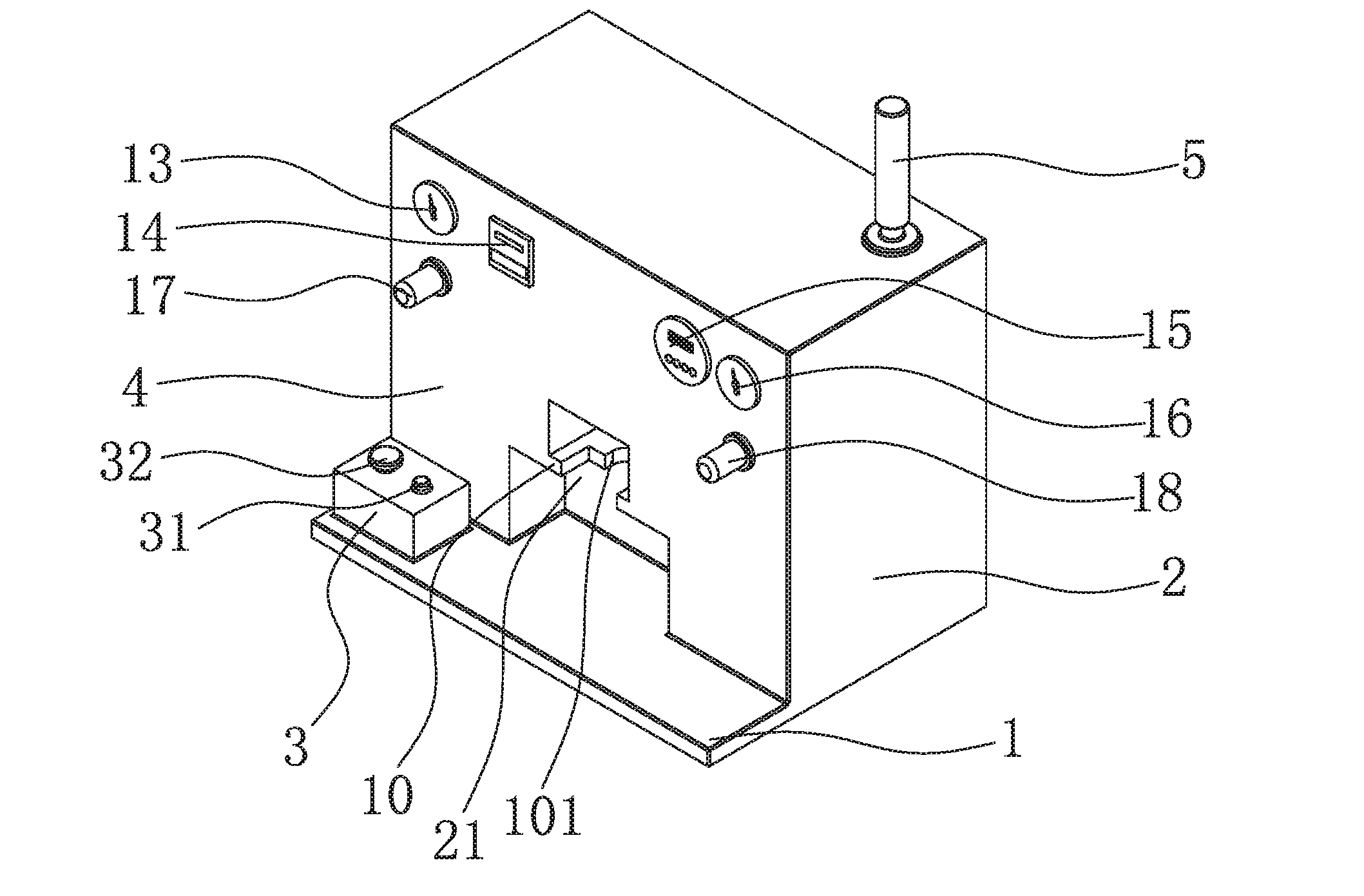
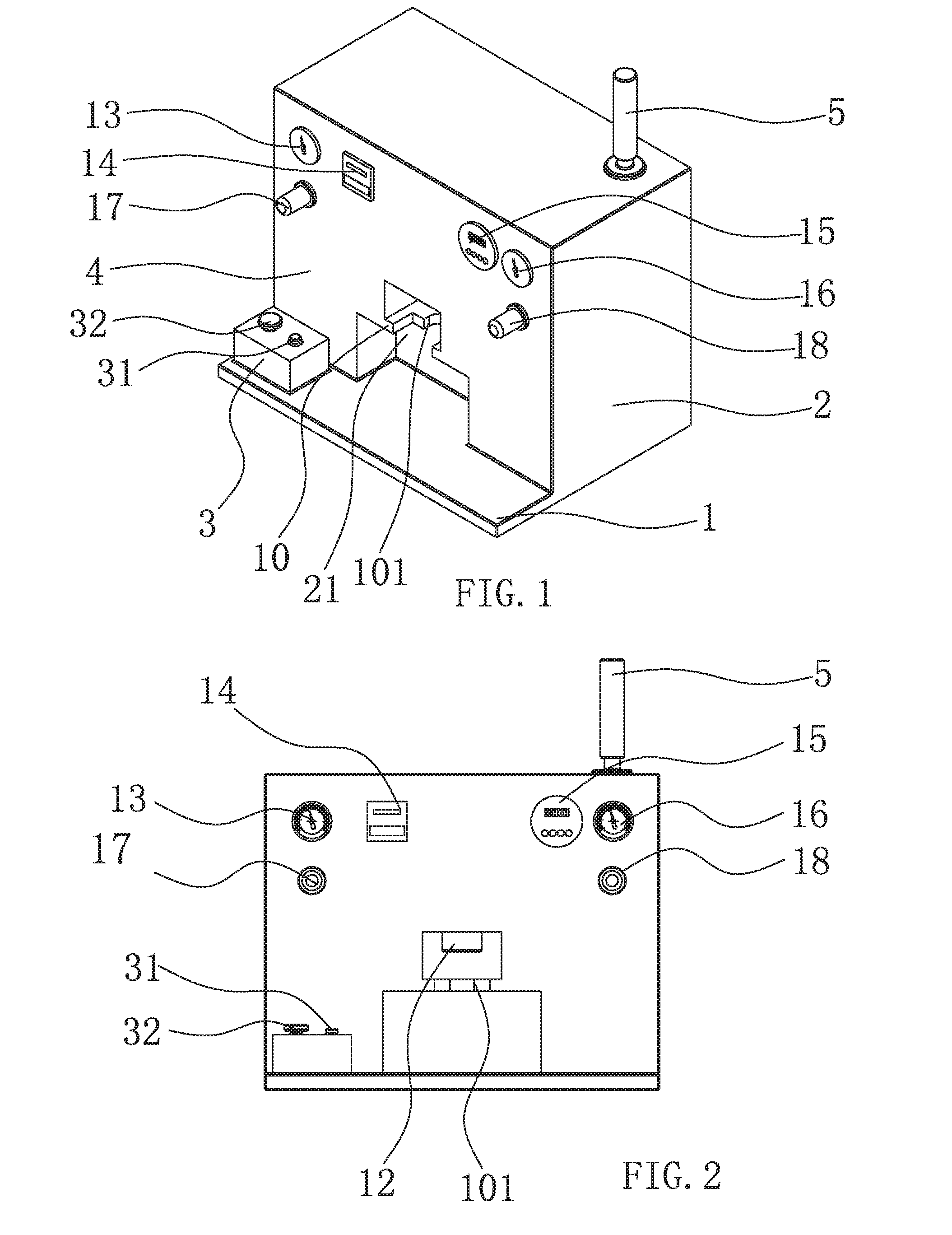
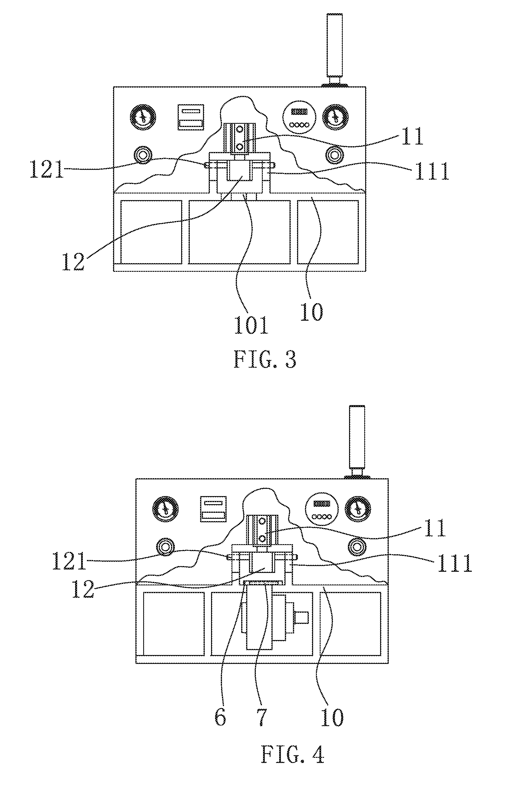
[0022]As shown in FIG. 1, air-tightness test equipment for a turbine reduction gearbox includes a base 1; an equipment housing 2 covers the base 1; a test cavity 21, a switch control box 3 and a control display panel 4 are arranged on the equipment housing 2; and an alarm 5 is arranged on the top right side of the equipment housing 2. The alarm 5 of the present invention includes an indicator light and a buzzer, wherein the indicator light includes a red display light, a yellow display light and a green display light. As shown in FIG. 1, FIG. 2, FIG. 3 and FIG. 4, a product mounting plate 10 is arranged inside the test cavity in the present invention, the product mounting plate 10 is provided with a product positioning slot 101 having an opening, on its one side, matched with a flange structure of the turbine reduction gearbox. A compression cylinder 11 which is mounted and fixed by a cylinder support plate 111 is arranged over the product mounting plate 10, the compression cylinder...


PUM


Abstract

The present invention discloses air-tightness test equipment for a turbine reduction gearbox, comprising a base, characterized in that a product mounting plate is arranged and fixed on the base by a support frame, the product mounting plate is provided with a product positioning slot having an opening on its one side; a compression cylinder is arranged over the product mounting plate by a cylinder support plate, the compression cylinder is vertically arranged, and a piston rod of the compression cylinder faces downward and a sealed connector corresponding to the upper part of the product positioning slot is fixed at the lower end of the piston rod; the sealed connector has a cavity in which an inflator is arranged, and the inflator is connected with an inflator bump by a pipeline; the inflator pump is provided with a gas filtration device, the pipeline is provided with a gas valve, and a gas pressure sensor is arranged on the pipeline between the gas valve and the inflator; the compression cylinder, the inflator bump, the gas valve and the gas pressure sensor are connected to a controller, respectively.

Description

TECHNICAL FIELD OF THE INVENTION[0001]The present invention relates to the field of test equipment, and in particular to air-tightness test equipment for a turbine reduction gearbox.BACKGROUND OF THE INVENTION[0002]During the usage of a turbine reduction gearbox, sometimes, oil leakage may be caused by defects such as the presence of sand holes, fine cracks and the like on the gearbox body or by insufficient tightness of the cover. In order to avoid the potential oil leakage of a turbine reduction gearbox during the operation, it is desired to perform an air-tightness test on the turbine reduction gearbox. In order to test the air-tightness of a turbine reduction gearbox, testers usually tests the air-tightness of the turbine reduction gearbox by immersing it in water. However, since whether the gearbox is tight or not depends upon a long period of observation by the testers, the automatic testing cannot be realized, and the labor intensity of the testers is increased. Sometimes, a ...

Claims


Application Information

Patent Timeline
IPC IPC(8): G01M3/02F04B43/02G01M15/02F01D21/00
CPCG01M3/025G01M15/02F04B43/02F01D21/003F04B51/00F02C7/36G01M13/02G01M3/32G01L9/08G01M3/02G01W1/11G08B21/182G08B21/187
Inventor SUN, ZHUBINGJIN, RONGHUADU, SHAN
Owner ZHEJIANG LINIX MOTOR
Why Eureka
Try Eureka