System And Method For Controlling Output Of A Battery Pack

a technology of output and battery pack, applied in the field of communication of the operating state of the battery pack, can solve the problems of vehicle driver's perception of objectionable wheel torque changes, vehicle drivability may be affected, battery degrade, etc., to reduce battery pack degradation and improve vehicle drivability

Active Publication Date: 2012-04-26
A123 SYSTEMS LLC
View PDF4 Cites 19 Cited by
  • Summary
  • Abstract
  • Description
  • Claims
  • Application Information

AI Technical Summary

Benefits of technology

[0004]One way to ensure that battery does not sink or source an amount of current that is greater than the threshold amount is for the battery pack to output a signal that represents an available current limit to a vehicle controller. By knowing the battery's available current limit the vehicle controller can limit current drawn or delivered to the battery by an electric motor or inverter. In this way, the possibility of battery degradation related to a quantity of current a battery sinks or sources may be reduced.
[0007]By providing an indication of a current limit and an indication of a capability of a battery to sink or source the amount of current at the available current limit, vehicle drivability issues related to dynamic changes in a battery pack's ability to sink or source current may be mitigated. In one example, a buffer signal is provided to a vehicle controller so that the vehicle controller can anticipate when the battery's current sourcing or sinking capability will change. The buffer signal can be related to a history of battery charge / discharge current, the present battery charge / discharge current, the transient charge / discharge current, and a ramp rate for transitioning from a transient current level to a continuous current level. Based on the signal indicating the battery available current limit and the signal representing the battery capability to supply current at the current limit, a vehicle controller can judge when to begin transitioning from a transient current level to a continuous current level. For example, a vehicle controller may determine when to limit current supplied to or drawn from a battery in response to the indicated available current limit and the indicated capability of the battery pack to sink or source current. In particular, if the battery current limit is high, but the battery capability to sink or source current is low, the vehicle controller may gradually (e.g., by ramping motor current) limit current flowing to or from the battery at a first rate. In another example, the vehicle controller may gradually limit battery current at a second rate depending on the rate of change in battery current sourcing or sinking capability as well as the present battery current sinking or sourcing capability. In another example, a vehicle controller may provide an extended amount of time (e.g., by ramping motor current at a third rate) for which current may be sourced or sunk by the battery when the level of battery current is above the continuous current limit but while the battery current is well below the available current limit. In this way, an available current limit signal and a battery capability signal may be used to improve vehicle drivability.
[0008]The present description may provide several advantages. In particular, the method can reduce battery pack degradation without having to replace hardware or rely on external systems. Further, the present description provides for additional measures of battery pack degradation protection. Further still, the level of threshold currents can be adjusted for different capability battery packs without having to change hardware and / or software.

Problems solved by technology

If a battery pack is supplying a relatively large amount of current during vehicle acceleration, the battery may degrade if the battery current is supplied in an amount greater than a threshold amount of current for longer than a specified time.
However, even though a vehicle controller may reduce current demand on a battery in response to an available current limit signal, the vehicle driver may perceive changes in wheel torque that may be objectionable.
Thus, vehicle drivability may be affected if a vehicle wheel torque is adjusted in this manner.

Method used


Image

  • System And Method For Controlling Output Of A Battery Pack
  • System And Method For Controlling Output Of A Battery Pack
  • System And Method For Controlling Output Of A Battery Pack

Examples


Embodiment Construction

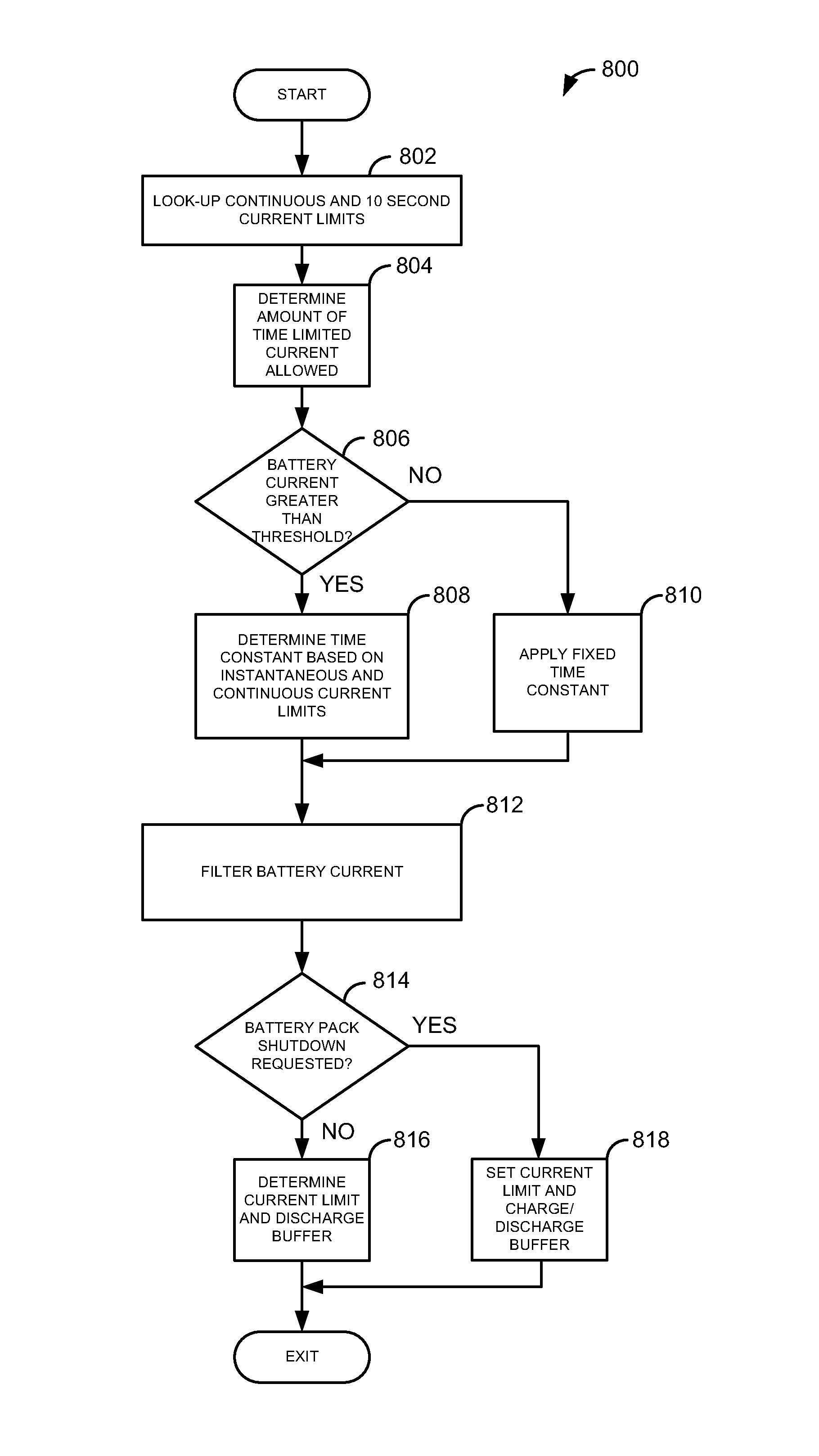
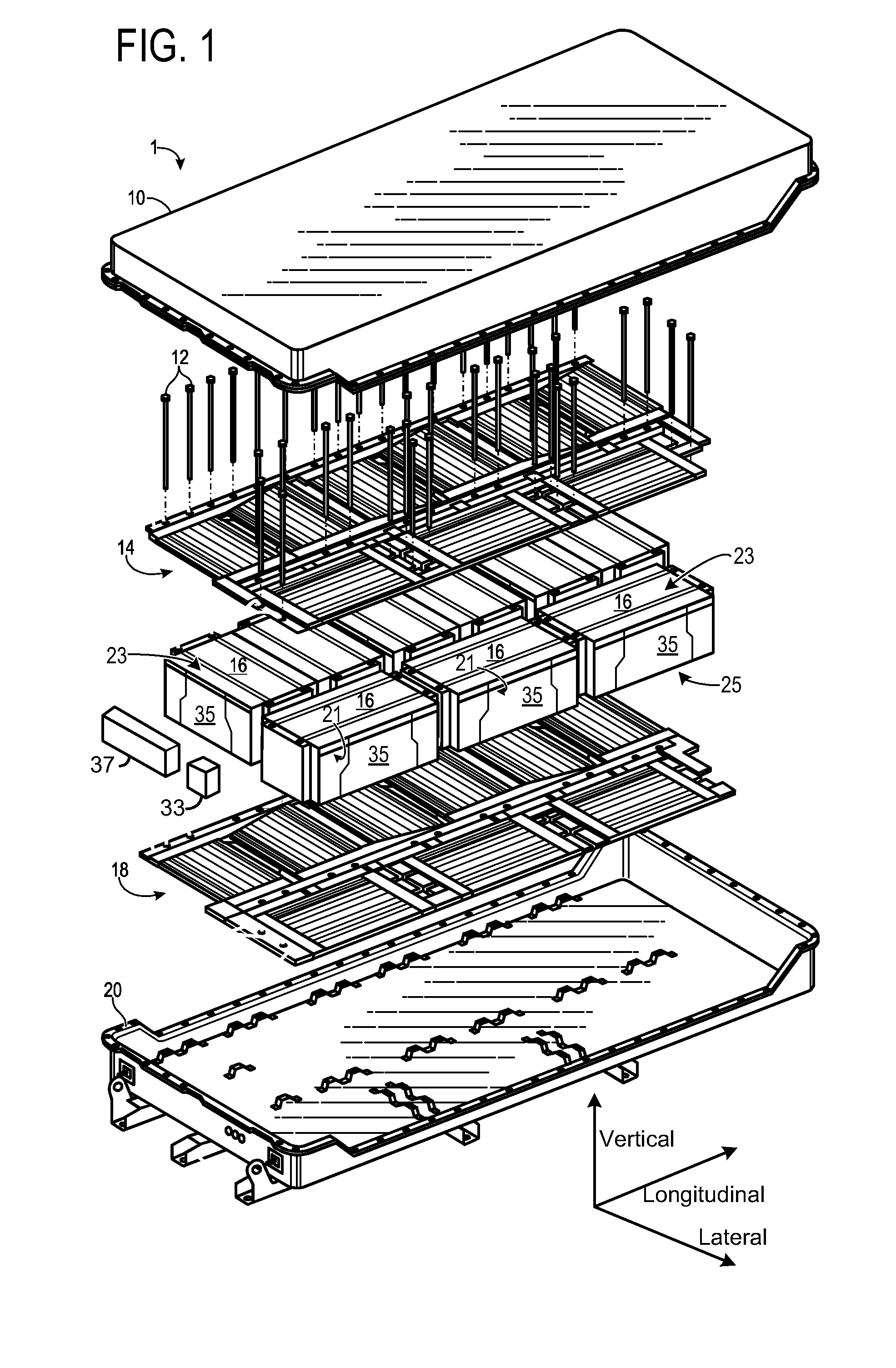
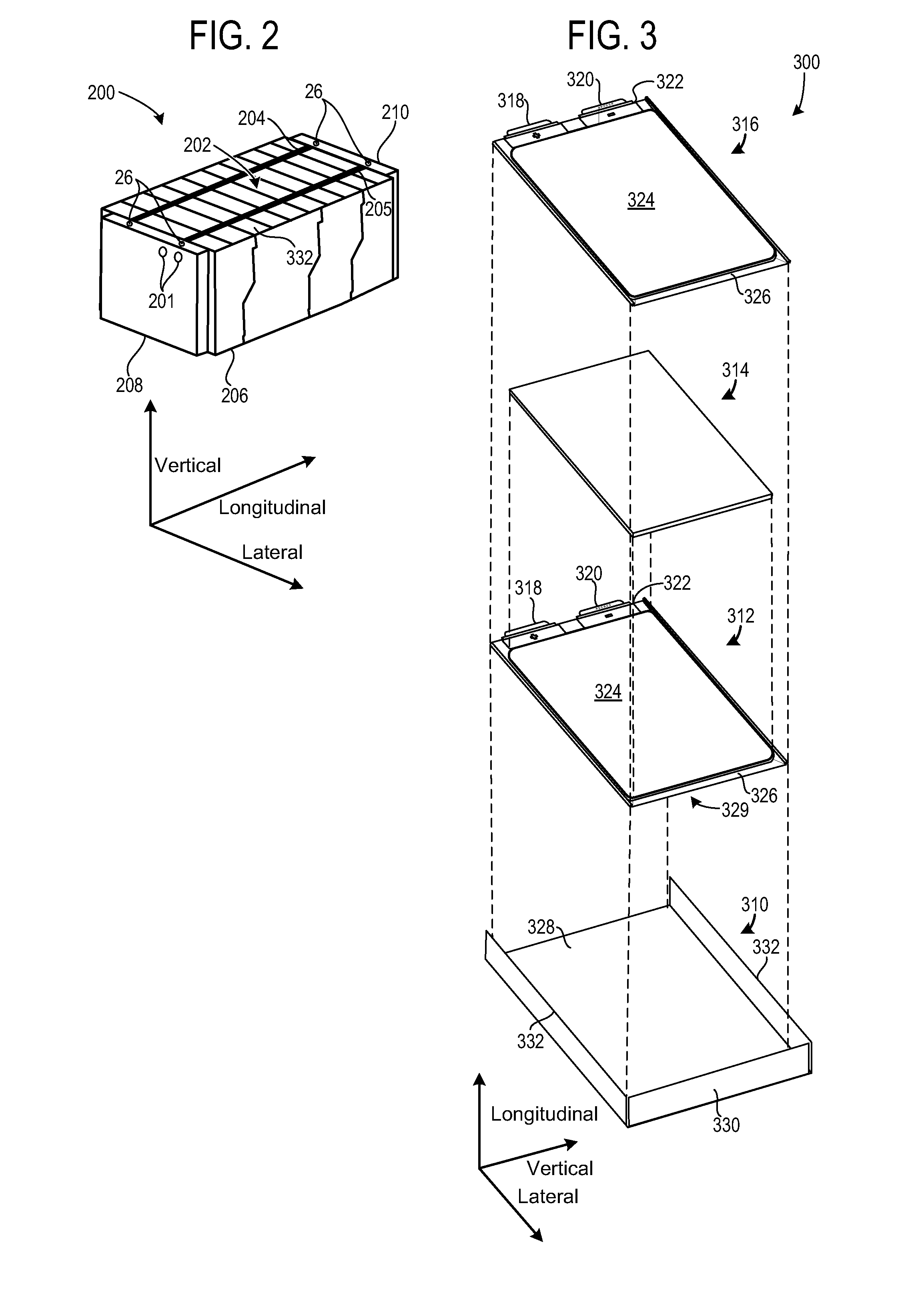
[0020]The present description is related to providing one or more signals to a controller external to a battery pack to improve vehicle drivability. In one embodiment, battery cells such as those illustrated in FIGS. 2-3 may be combined in a battery pack as illustrated in FIG. 1. The power from the battery cells of FIGS. 1-3 may be selectively delivered to a load external to the battery pack via a contactor as shown in FIG. 4. In one example illustrated by the method of FIGS. 7-8, a battery pack outputs a first signal that indicates battery available current limit and a second signal indicating a capability of the battery pack to sink or source an amount of current at the available current limit. FIGS. 5-6 show example signals of interest provided by the method of FIGS. 7-8.

[0021]FIG. 1 shows an exploded view of a battery assembly 1. The battery assembly may include a cover 10, coupling devices 12, a first cooling subsystem 14 (e.g., cold plate), a plurality of battery modules 16, a...


PUM

PropertyMeasurementUnit
timeaaaaaaaaaa
timeaaaaaaaaaa
currentaaaaaaaaaa

Abstract

Systems and methods for communicating a state of a battery to a vehicle controller are disclosed. In one example, a battery pack outputs a signal indicative of an amount of capability the battery pack has to source or sink current at present operating conditions. The system and method may improve vehicle drivability and reduce battery pack degradation.

Description

CROSS REFERENCE TO RELATED APPLICATIONS[0001]This application claims priority from U.S. Provisional Patent Application Ser. No. 61 / 185,772, filed Jun. 10, 2009 and entitled BATTERY LIMIT BUFFER, the entirety of which is hereby incorporated herein by reference for all intents and purposes.TECHNICAL FIELD[0002]The present description relates to communicating an operating state of a battery pack. In one example, the battery pack provides power to a vehicle.BACKGROUND AND SUMMARY[0003]A battery pack may supply power to propel a vehicle. Alternatively, the battery pack may receive or sink power when the vehicle is decelerating. When a battery pack is sinking or sourcing current it has continuous current sinking and sourcing capacities as well as transient sinking and sourcing capacities. If a battery pack is supplying a relatively large amount of current during vehicle acceleration, the battery may degrade if the battery current is supplied in an amount greater than a threshold amount of...

Claims


Application Information

Patent Timeline
Patent Type & Authority Applications(United States)
IPC IPC(8): G01N27/416H01M50/211
CPCB60W2510/244G01R31/3658H01M2/1077H01M10/48Y02T90/16B60L11/1861Y02T10/7044Y02T10/7005Y02T10/705H01M10/486B60L58/12G01R31/396Y02T10/70Y02E60/10H01M50/211H01M10/482H01M10/425H01M10/4207H01M2010/4278H01M2220/20
Inventor RUTKOWSKI, BRIAN D.MOORHEAD, BRIAN C.
Owner A123 SYSTEMS LLC
Why Eureka
Try Eureka