Gate driver unit for electrical switching device

a technology of electrical switching device and gate driver, which is applied in the direction of power conversion system, oscillation generator, pulse technique, etc., can solve the problems of uneven wear and tear of the switching device, unbalanced current distribution, and seldom evenly balanced current through the switching devi

Active Publication Date: 2012-04-26
ABB (SCHWEIZ) AG
View PDF6 Cites 34 Cited by
  • Summary
  • Abstract
  • Description
  • Claims
  • Application Information

AI Technical Summary

Benefits of technology

[0022]An advantage of an exemplary method and apparatus of the present disclosure is that there is no longer a need for derating of parallel-connected power switching devices, or adding passive components to balance the currents, in dynamic switching events. The cost is therefore reduced. Removing the additional passive components also reduces total power losses.
[0009]An exemplary method for controlling a plurality of switching devices through at least one intelligent gate driver unit is disclosed. For each intelligent gate driver unit, the method comprises receiving turn-on and turn-off commands for a switching device, receiving feedback information on turn-on and turn-off events of one of the switching devices; receiving reference information on turn-on and turn-off events of another switching device; calculating a value for a control parameter on the basis of the reference information and feedback information; and controlling, on the basis of a switching device command and the control parameter, a control signal at control outputs of the intelligent gate driver unit, the output being connected to the control terminal of the switching device.

Problems solved by technology

A known problem associated with the parallel-connected switching devices is that currents through the switching devices are seldom evenly balanced. FIG. 1 illustrates examples of uncompensated schematic current waveforms for three parallel-connected IGBTs in accordance with known systems.
The waveforms show unbalanced current distribution due to differentiating turn-on and turn-off times. Unbalanced currents cause uneven wear and tear in the switching devices.
The uneven wear and tear in turn reduces the lifetime of the switching devices.
Further, unbalanced currents may cause a switching device to reach its maximum temperature rating or maximum current rating faster than when the currents are in balance.
However, this approach can be inefficient and costly.
However, handpicking the components adds production costs.
The disclosed method requires a relatively complex measurement and communication system to operate.

Method used


Image

  • Gate driver unit for electrical switching device
  • Gate driver unit for electrical switching device
  • Gate driver unit for electrical switching device

Examples


Embodiment Construction

[0019]Exemplary embodiments of the present disclosure are directed to providing a method and an apparatus for implementing the method to alleviate the above disadvantages.

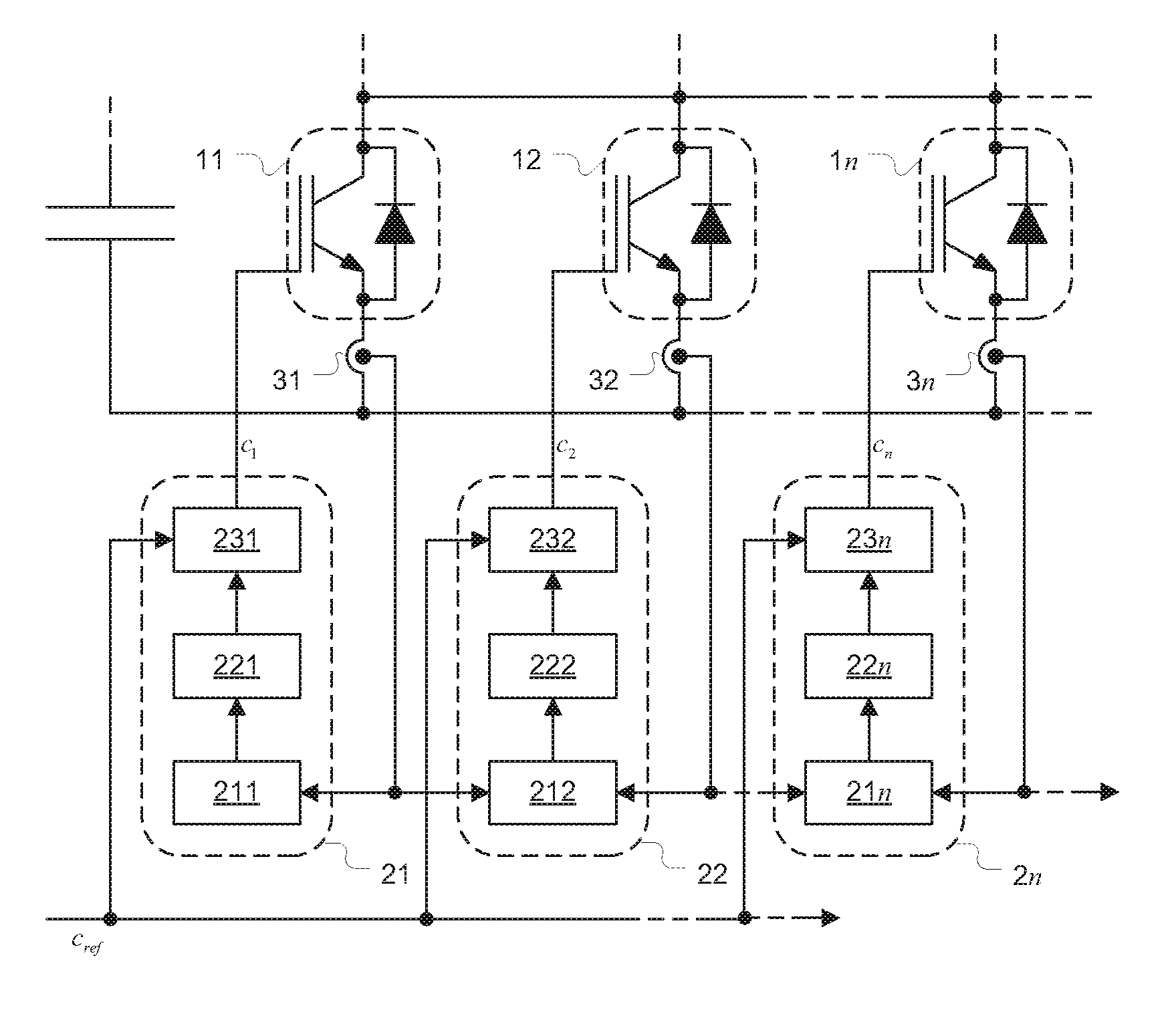
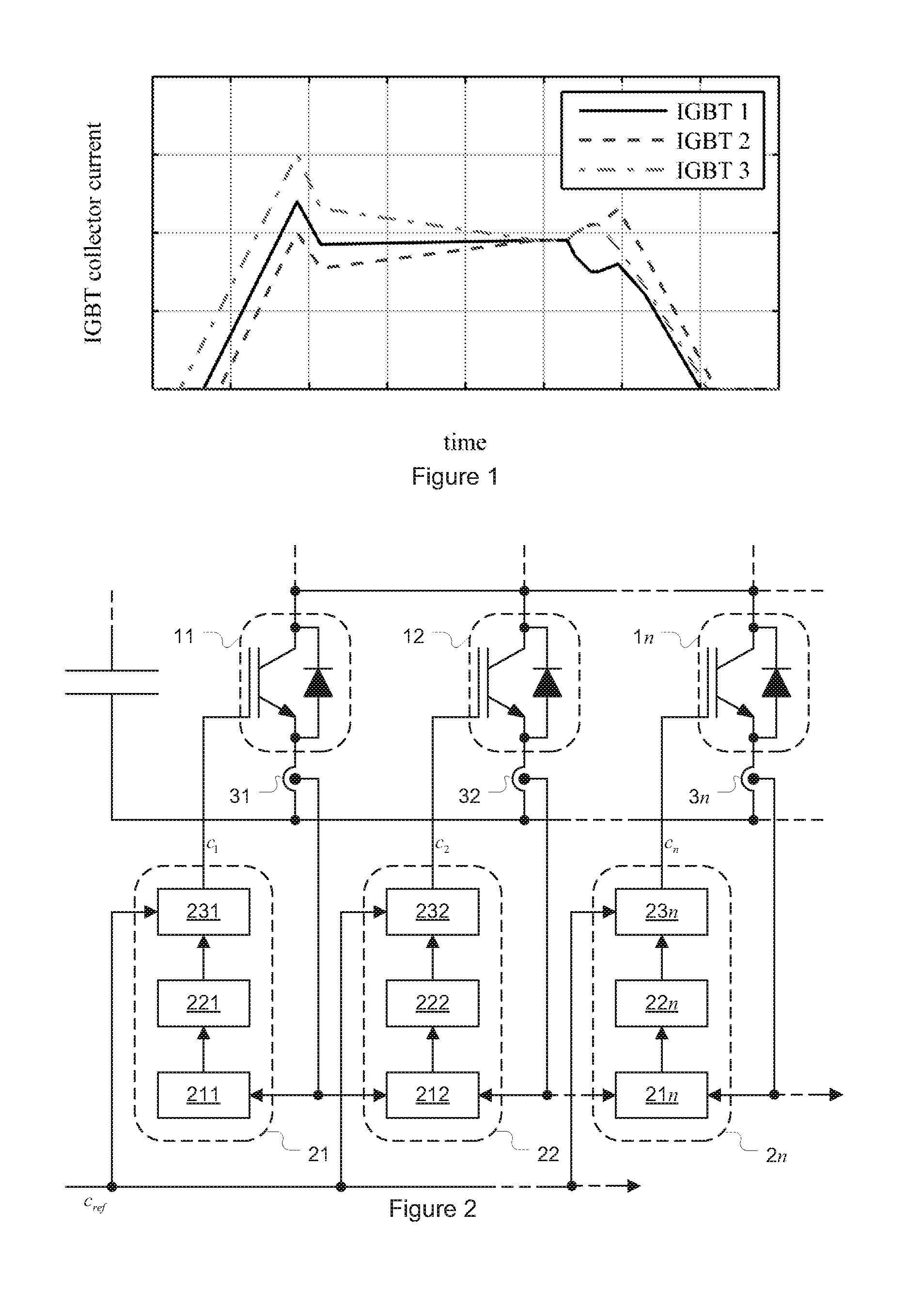
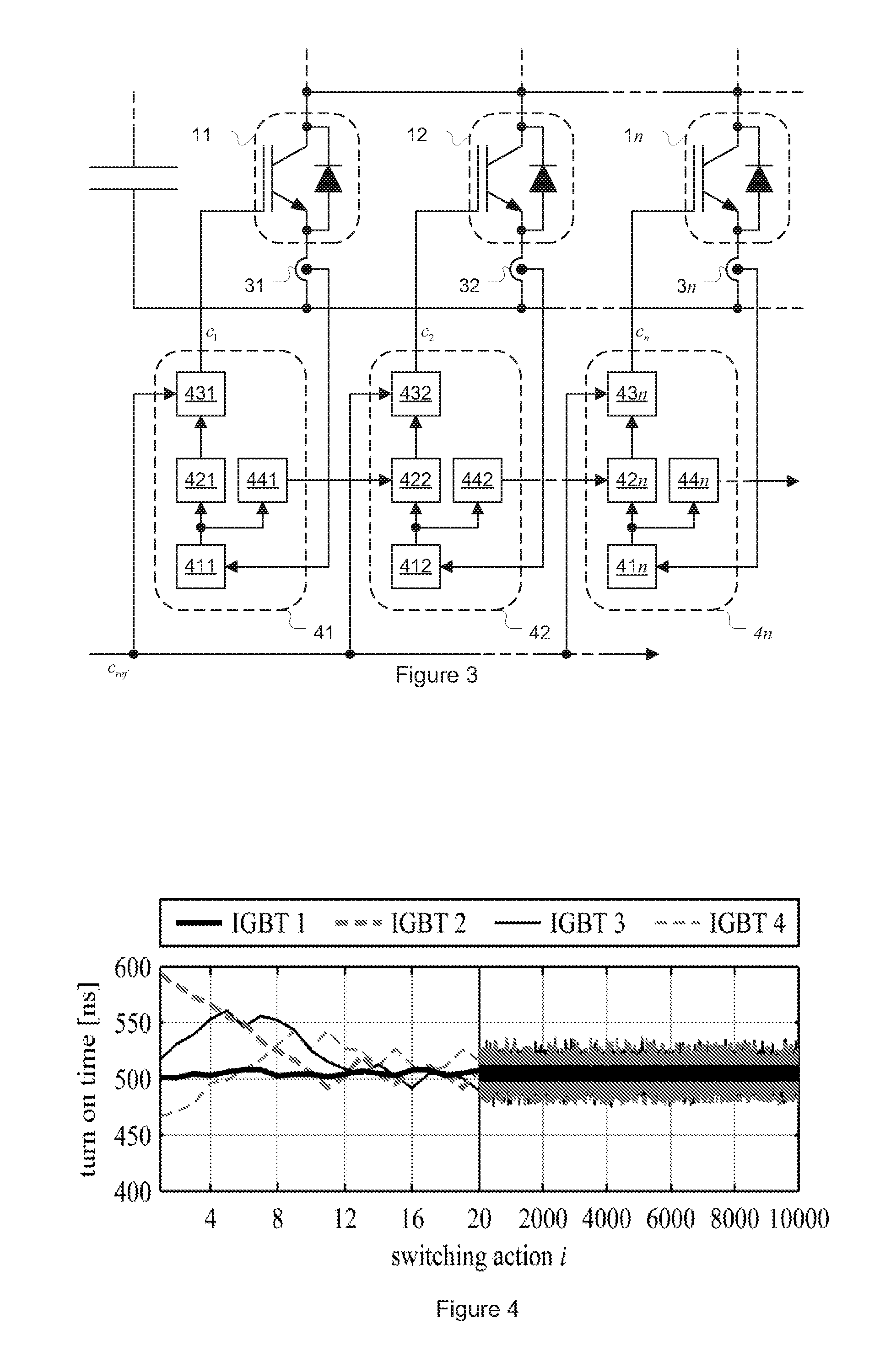
[0020]The exemplary embodiments use intelligent gate driver units (IGDU) with distributed intelligence to control parallel-connected electrical switching devices such as IGBTs, for example. The intelligence balances the currents of the switching devices, even in dynamic switching events. The IGDUs execute specified measurements independently and establish a specified communication between each other. They may use master-slave or daisy chain control structures and instantaneous or time integral differences of the currents of parallel-connected switching devices as control parameters.

[0021]In addition, instead of balancing the currents, the temperature can also be balanced with the intelligent gate driver units. Furthermore, the concept can also be applied to balance the voltages of antiparallel power modules.

[0022]A...


PUM


Abstract

An exemplary apparatus and method for using intelligent gate driver units with distributed intelligence to control antiparallel power modules or parallel-connected electrical switching devices like IGBTs is disclosed. The intelligent gate drive units use the intelligence to balance the currents of the switching devices, even in dynamic switching events. The intelligent gate driver units can use master-slave or daisy chain control structures and instantaneous or time integral differences of the currents of parallel-connected switching devices as control parameters. Instead of balancing the currents, temperature can also be balanced with the intelligent gate driver units.

Description

RELATED APPLICATION[0001]This application claims priority under 35 U.S.C. §119 to European Patent Application No. 10188454.2 filed in Europe on Oct. 22, 2010, the entire content of which is hereby incorporated by reference in its entirety.FIELD[0002]The present disclosure relates to electrical switching devices, such as controlling gate-controlled electrical switching devices, such as MOSFETs, IGBTs, and BJTs, for example.BACKGROUND INFORMATION[0003]Parallel-connected switching devices can be used in applications where high current throughput is specified. The parallel connection is used in inverter bridges feeding high current AC- or DC-loads.[0004]A known problem associated with the parallel-connected switching devices is that currents through the switching devices are seldom evenly balanced. FIG. 1 illustrates examples of uncompensated schematic current waveforms for three parallel-connected IGBTs in accordance with known systems. The waveforms show unbalanced current distributio...

Claims


Application Information

Patent Timeline
Patent Type & Authority Applications(United States)
IPC IPC(8): G05F1/02
CPCH02M1/088H03K17/082H03K17/30H03K17/12H03K17/28H03K17/10
Inventor LOBSIGER, YANICKBORTIS, DOMINIKKOLAR, JOHANN WALTERLAITINEN, MATTI
Owner ABB (SCHWEIZ) AG
Why Eureka
Try Eureka