Touch module

a module and touch technology, applied in the field of touch modules, can solve the problems of increasing material cost, noise, complicated manufacturing procedure, etc., and achieve the effect of reducing material cost and simplifying the manufacturing process

Inactive Publication Date: 2012-04-26
SENTELIC TECH CO LTD
View PDF2 Cites 17 Cited by
  • Summary
  • Abstract
  • Description
  • Claims
  • Application Information

AI Technical Summary

Benefits of technology

[0016]It is therefore a primary object of the present invention to provide a touch module, which is manufactured without any paint-made frame, so that the manufacturing process is simplified and the cost for the material is lowered. In addition, the touch module has a tidy and beautified appearance.
[0017]It is a further object of the present invention to provide the above touch module in which the connection circuit is directly concealed by the case so that the touch module is protected from any interference of external signal. Only the section corresponding to the sensors is exposed to outer side of the case so that the possibility of misjudgment and mis-touch is minimized.
[0018]It is still a further object of the present invention to provide the above touch module, which has better waterproof effect and is free from the problem of alignment in assembling process. Also, the touch module has better connection strength.

Problems solved by technology

This process complicates the manufacturing procedure and the paint 71 leads to increase of material cost.2. The connection circuit 82 tends to produce noises to interfere with the operation when the finger touches the touch panel without isolation layer.3. Except the colored frame, the surface of the transparent panel 7 is not provided with any means for distinguishing the position of the connection circuit 82.
Due to the seams along the periphery of the touch panel, the touch panel can be hardly waterproof-treated.
This process complicates the manufacturing procedure and the paint 92 leads to increase of material cost.2. The transparent sheet 91 will increase the total thickness of the product.3. It is hard to precisely locate and align the transparent panel 70 with the case 9.4. The transparent sheet 91 will lead to incorrectness of the touch sensing signal and deterioration of transparency.

Method used


Image

  • Touch module
  • Touch module
  • Touch module

Examples


first embodiment

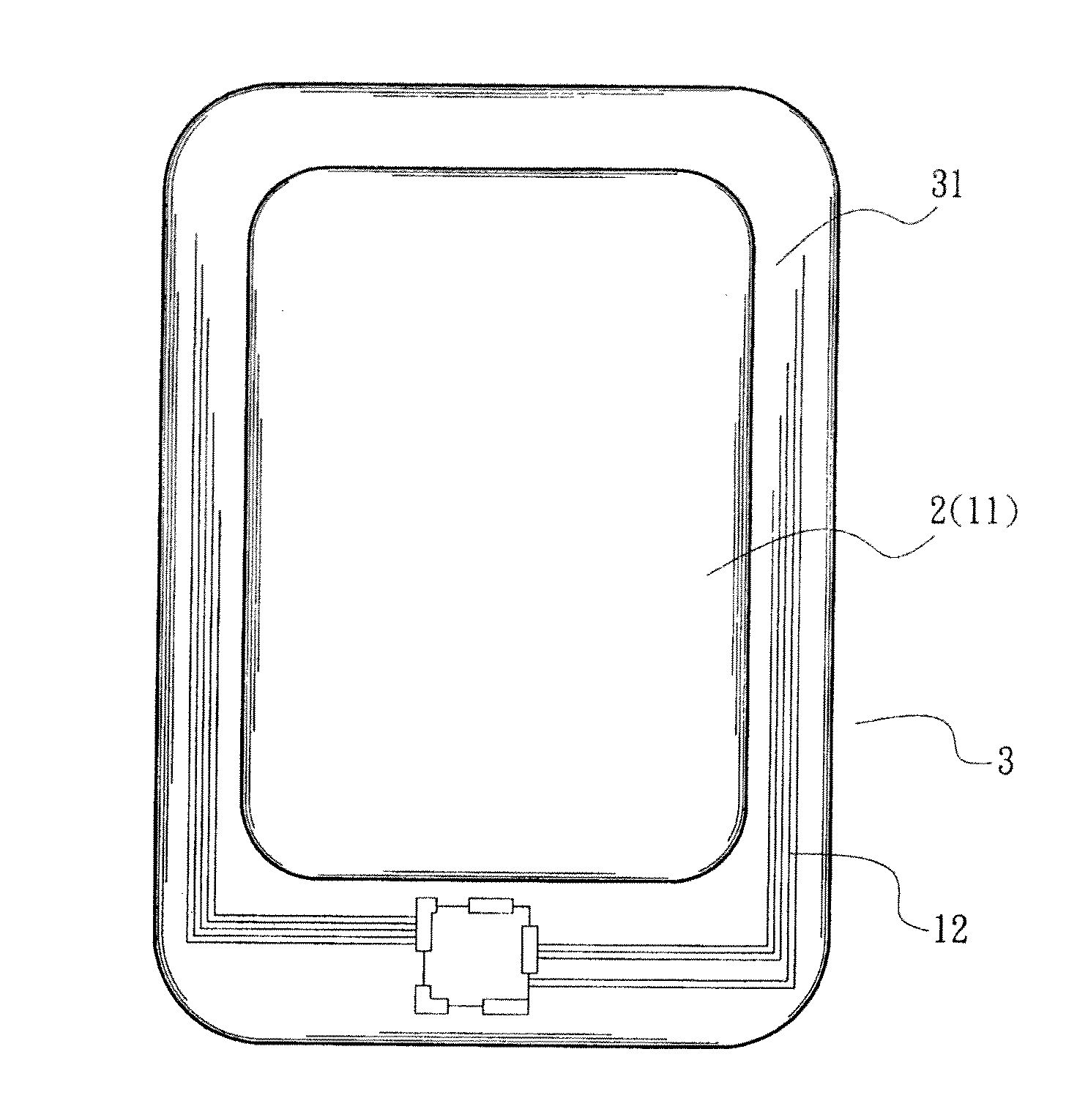
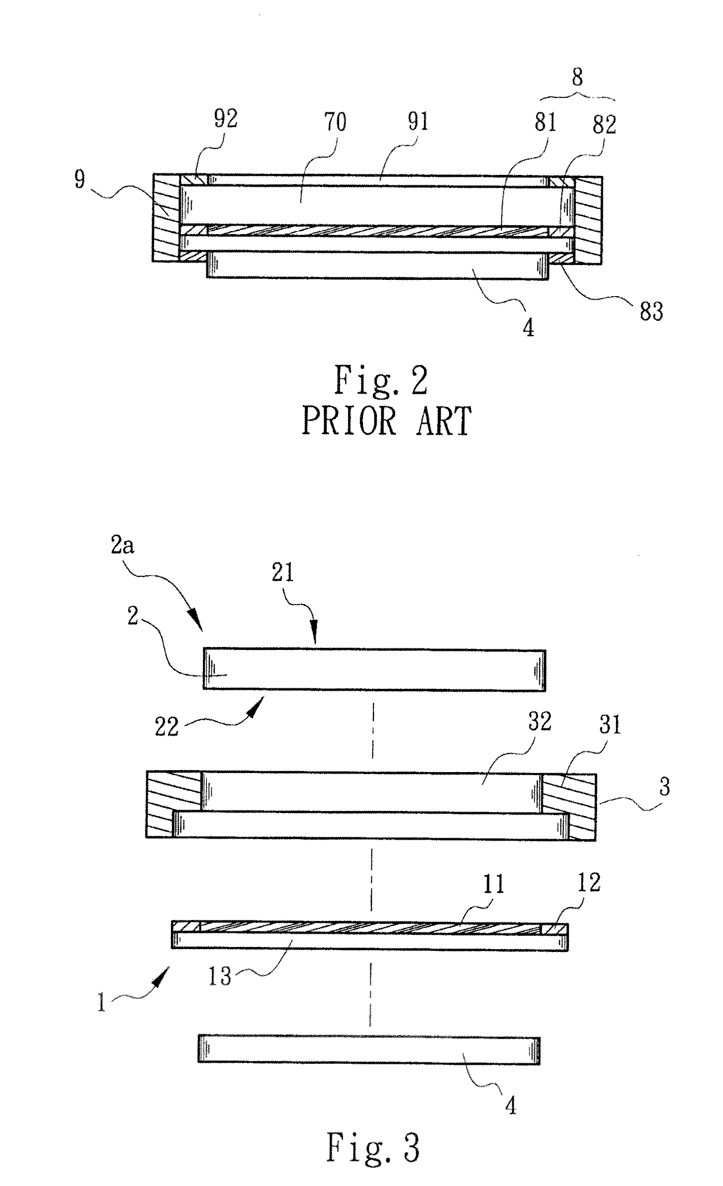
[0038]Please refer to FIGS. 3 to 3B. the touch module of the present invention mainly includes a touch layer 1, a transparent panel module 2a and a case 3. The touch layer 1 is composed of multiple sensors 11 for sensing the touch and a connection circuit 12 arranged around the sensors 11. The multiple sensors 11 and the connection circuit 12 can be formed on a sheet-shaped transparent protective element 13 as necessary.

[0039]In this embodiment, the transparent panel module 2a is a one-piece transparent panel 2 made of transparent material. The transparent panel 2 has a first side 21 and a second side 22 opposite to the first side 21. The second side 22 is directly bonded with the sensors 11 of the touch layer 1. The connection circuit 12 is formed along at least a part of the periphery of the transparent panel 2. In practice, a liquid crystal module layer 4 is additionally disposed under the sensors 11 of the touch layer 1. The liquid crystal module layer 4 not only serves to disp...

fourth embodiment

[0045]Please refer to FIGS. 6 and 6A, which show the present invention. According to the fourth embodiment, the touch module of the present invention includes a touch layer 1 and liquid crystal module layer 4 as in the first embodiment. The fourth embodiment further includes a transparent panel module 6a and a case 30. In this embodiment, the transparent panel module 6a is a one-piece transparent panel 6 made of transparent material. The transparent panel 6 has a first side 61 and a second side 62 opposite to the first side 61. The first side 61 includes at least one first surface 611 and at least one second surface 612. The first and second surfaces 611, 612 are positioned on different levels of the transparent panel 6. The second side 62 has a sensing section 621 corresponding to and opposite to the first surface 611 and a wiring section 622 corresponding to and opposite to the second surface 612. The sensing section 621 and the wiring section 622 of the second side 62 of the tran...

sixth embodiment

[0047]Please refer to FIG. 8, which show the present invention. According to the sixth embodiment, the touch module of the present invention includes a touch layer 1, a case 300, a liquid crystal module layer 4 and a transparent panel module 6a as in the fourth embodiment. The transparent panel module 6a (transparent panel 6) is fixed in the opening of the case 300. The other components of the touch layer 1 and the liquid crystal module layer 4 are totally identical to those of the fourth embodiment in structure and positional relationship. The sixth embodiment is only different from the fourth embodiment in that the sixth embodiment further includes a transparent sheet 303 disposed in the opening of the case 300 over the transparent panel module 6a. The transparent sheet 303 serves as a protective shield in adaptation to the case 300 with a different configuration for achieving better waterproof protection.


PUM


Abstract

A touch module includes a touch layer, a transparent panel module and a case. The touch layer has at least one sensor and a connection circuit arranged at least partially around the sensor. The transparent panel module is bonded with one side of the touch layer to at least cover the sensor. The case is formed with an opening for receiving the transparent panel module, whereby the transparent panel module is at least partially exposed to outer side. An inner flange is formed along at least a part of the periphery of the opening for concealing where the connection circuit of the touch layer is positioned to achieve better interference protection effect and minimize the possibility of misjudgment and mis-touch.

Description

BACKGROUND OF THE INVENTION[0001]1. Field of the Invention[0002]The present invention relates generally to a touch module, and more particularly to a touch module with thinner thickness and better interference protection.[0003]2. Description of the Related Art[0004]Following the rapid development of information technologies and communication networks, electronic information products have more and more popularly used in various fields. The capacitive touch panel has become the mainstream of touch control technology. The capacitive touch panel is widely applied to various electronic information products such as cellular phones, laptop computers, walkmans, displays, monitors and AIO. The capacitive touch panel works on the principle that when a finger touches the capacitive touch panel, the capacitance will change to measure the displacement of the finger so as to achieve the object of operation / control.[0005]FIGS. 1 and 1A show a conventional simple capacitive touch panel applied to a...

Claims


Application Information

Patent Timeline
Patent Type & Authority Applications(United States)
IPC IPC(8): G06F3/041
CPCG06F3/044G06F2203/04107G06F2203/04103G06F3/04164G06F3/0443
Inventor LIN, JAO-CHINGCHU, LIN ABELSHEN, CHUNG YI
Owner SENTELIC TECH CO LTD
Why Eureka
Try Eureka