Method and apparatus for optimally laser marking articles

a laser marking and laser pulse technology, applied in the field of laser marking articles, can solve the problems of uneven and commercially unacceptable, unacceptably low throughput, different damage thresholds, etc., and achieve the effect of increasing the fluence of the initial laser pulse, reducing damage thresholds, and increasing throughput of laser marking systems

Inactive Publication Date: 2012-04-26
ELECTRO SCI IND INC
View PDF4 Cites 35 Cited by
  • Summary
  • Abstract
  • Description
  • Claims
  • Application Information

AI Technical Summary

Benefits of technology

[0012]Aspects of this invention control the output of the laser. In order to facilitate application of tool paths as selected by this invention, laser pulse fluence should be attenuated very precisely under the control of the laser marking system. Aspects of this invention control the laser irradiance with sufficient precision to permit tool paths which create marks with commercially desirable uniformity, color, texture and shape. An optical switch is used to switch the laser beam on and off rapidly without requiring the laser to be turned off and on. Aspects of this invention use an acousto-optic modulator (AOM) to modulate the beam precisely and quickly and thereby direct the beam either to impinge the article or travel harmlessly to a beam dump.

Problems solved by technology

The difficulty is that these thresholds can be different for different areas of the mark at different times during the marking process.
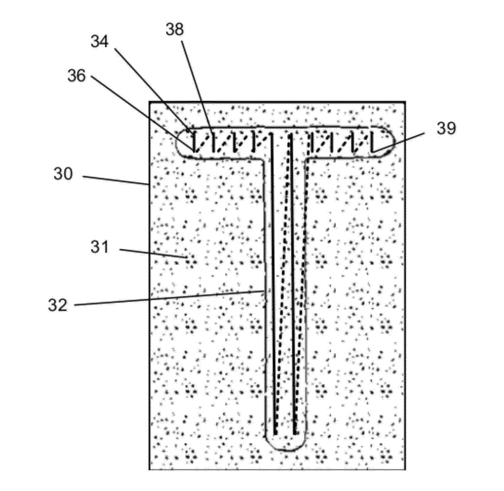
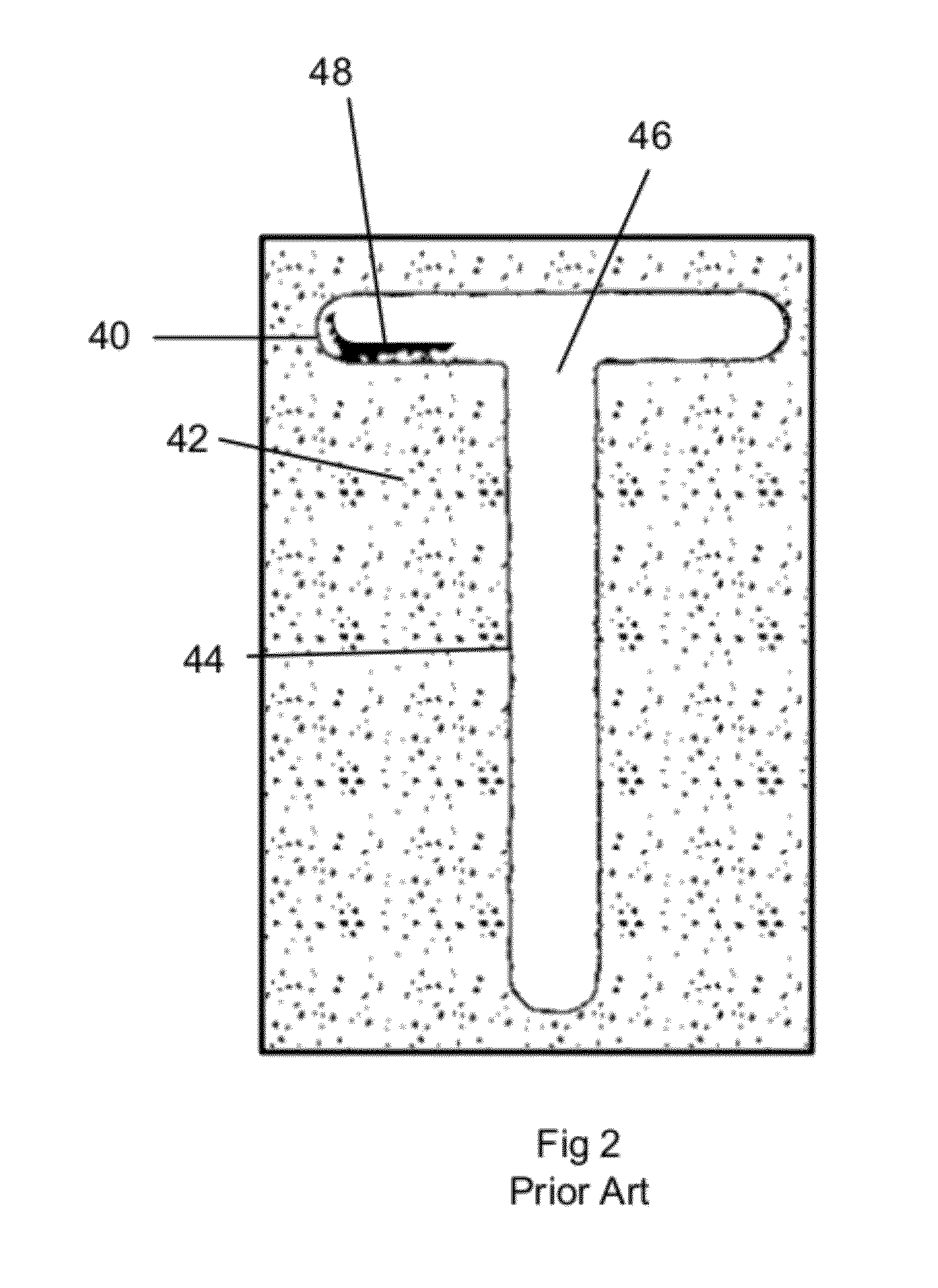
Laser parameters which provide commercially desirable appearance and acceptable rate of material removal and hence throughput in one area of the mark may damage the underlying material in another area of the mark. FIG. 2 shows the results of laser marking an article with a single irradiance and rate of travel, wherein the results are uneven and commercially unacceptable.
Choosing a single set of laser parameters which results in commercially desirable appearing mark may be possible but the resulting rate of material removal must not exceed the fastest acceptable removal rate for the all portions of the mark, resulting in unacceptably low throughput.
Therefore simply measuring laser fluence will not properly predict the appearance of the material following laser processing.
This is because previous irradiation of the location or nearby locations will tend to heat the material.

Method used


Image

  • Method and apparatus for optimally laser marking articles
  • Method and apparatus for optimally laser marking articles
  • Method and apparatus for optimally laser marking articles

Examples


Embodiment Construction

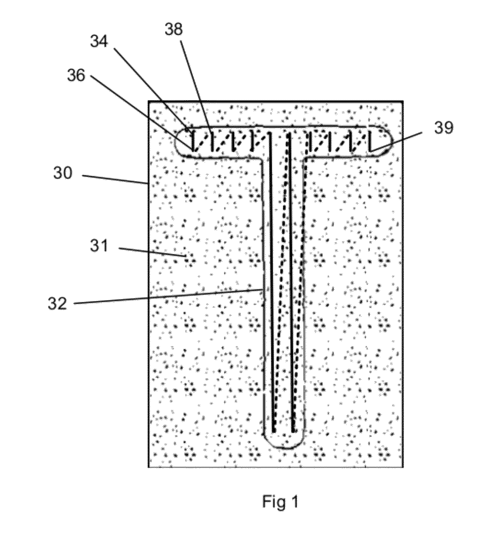
[0028]An embodiment of this invention creates a mark with desired properties on coated articles using a laser marking system. The laser marking system has controllable laser fluence or dose. Embodiments of this invention determine a first laser fluence associated with creating a mark with desired properties on a first portion of the mark. Aspects of this invention then determine a second laser fluence associated with creating a mark with desired properties on a second portion of the mark. These fluences are then stored in the laser marking system's storage. The laser marking system is then directed to mark the article using the stored first laser fluence in the first portion of the mark and using the stored second laser fluence in a second portion of the mark thereby marking the article with desired properties. Embodiments of this invention control laser fluence by controlling various laser parameters including laser pulse parameters such as pulse duration or pulse repletion rate, a...


PUM

PropertyMeasurementUnit
poweraaaaaaaaaa
poweraaaaaaaaaa
poweraaaaaaaaaa

Abstract

The present invention relates to laser marking articles. In particular it relates to laser marking articles by laser ablating a coating applied to the article which reveals the surface of the article underneath, thereby forming the mark by the contrasting appearance between the revealed surface of the article and the adjacent remaining coating. Laser parameters are selected to provide uniform, commercially desirable appearance and avoid damage to the underlying surface while maintaining acceptable system throughput. In particular the laser pulse envelope is tailored to provide desirable appearance while maintaining acceptable system throughput.

Description

TECHNICAL FIELD[0001]The present invention relates to laser marking articles. In particular it relates to laser marking articles by laser ablating a coating applied to the article which reveals the surface of the article underneath, thereby forming the mark by the contrasting appearance between the revealed surface of the article and the adjacent remaining coating. The mark may also be formed by laser ablating the first or topmost coating layer to reveal a second coating layer underneath forming the mark by the contrast between the revealed second coating and adjacent first coating. Laser parameters are selected to provide uniform, commercially desirable appearance and avoid damage to the underlying surface while maintaining acceptable system throughput. In particular the laser pulse envelope is tailored to provide desirable appearance while maintaining acceptable system throughput.BACKGROUND OF THE INVENTION[0002]Marketed products commonly require some type of marking on the produc...

Claims


Application Information

Patent Timeline
Patent Type & Authority Applications(United States)
IPC IPC(8): B32B3/00B23K26/00
CPCB23K26/063B23K26/36Y10T428/24802B23K26/4095B41M5/24B23K26/409B23K26/40B23K26/0622B23K2101/35B23K2103/172
Inventor BROOKHYSER, JAMESBALL, KYLE
Owner ELECTRO SCI IND INC
Why Eureka
Try Eureka